Spot Welder ✅
For the custom batteries I want to make for my HV Power Supply and 120VAC 60Hz inverter projects, I will need to spot weld nickel strips onto the terminals of the cells.
Last week I borrowed a spot welder from a coworker at my company and tried it at home, but the current output was too low and my test of one nickel strip on top of another resulted in very little meaningful welding. All attempted welds just pulled apart easily with barely any force. Thus I was stumped and needed to find my own way to spot weld 21700 or 18650 cells.
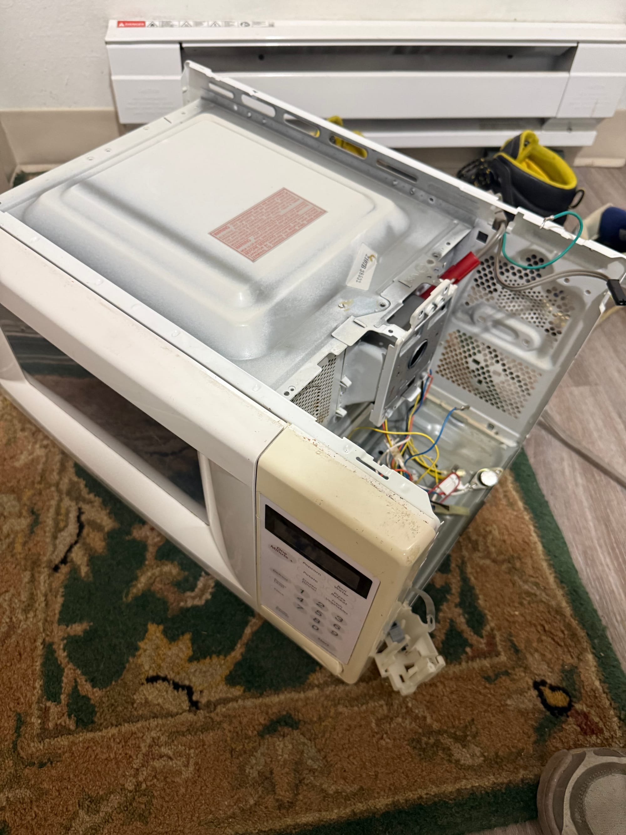
Luckily, at my apartment in the place near the stairwell where people drop off items they want to give away sometimes, I saw a microwave! Bingo!
I took it home today and dissassembled it for the transformer in order to make my own DIY spot welder like this TKOR video I remember watching as a kid. I have a lot of components that would work well to make this, and the general idea is really simple, so here is my plan:
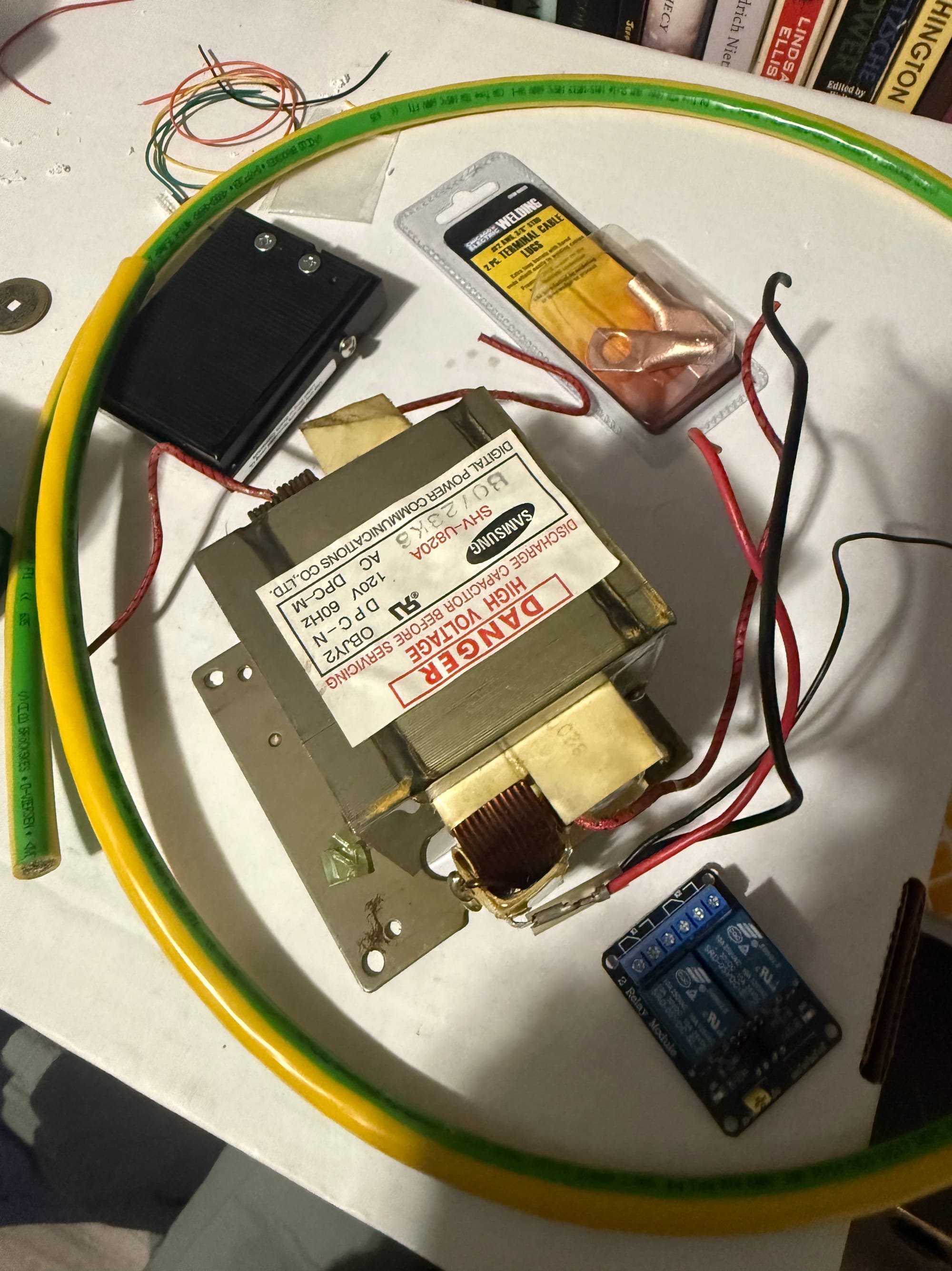
- Obtain transformer from microwave, remove the secondary (thin wire) winding via a hacksaw and hammer+chisel, and then put 2-4 turns of 2 AWG wire into the window where the HV secondary used to be.
- Use an extension cord and splice a mains relay into the current path, then use a 555 timer 20-200ms pulse circuit triggered by a foot switch in order to drive the logic side of the relay. Power the 555 timer from a 9v battery.
- Crimp 2AWG M6 copper lugs to the end of the new secondary winding with the M6 end filed down to create sharp contactor points. Use heatshrink tubing or electrical tape for the handles.
- Connect the extension cord with the relay in between the transformer and the wall outlet.
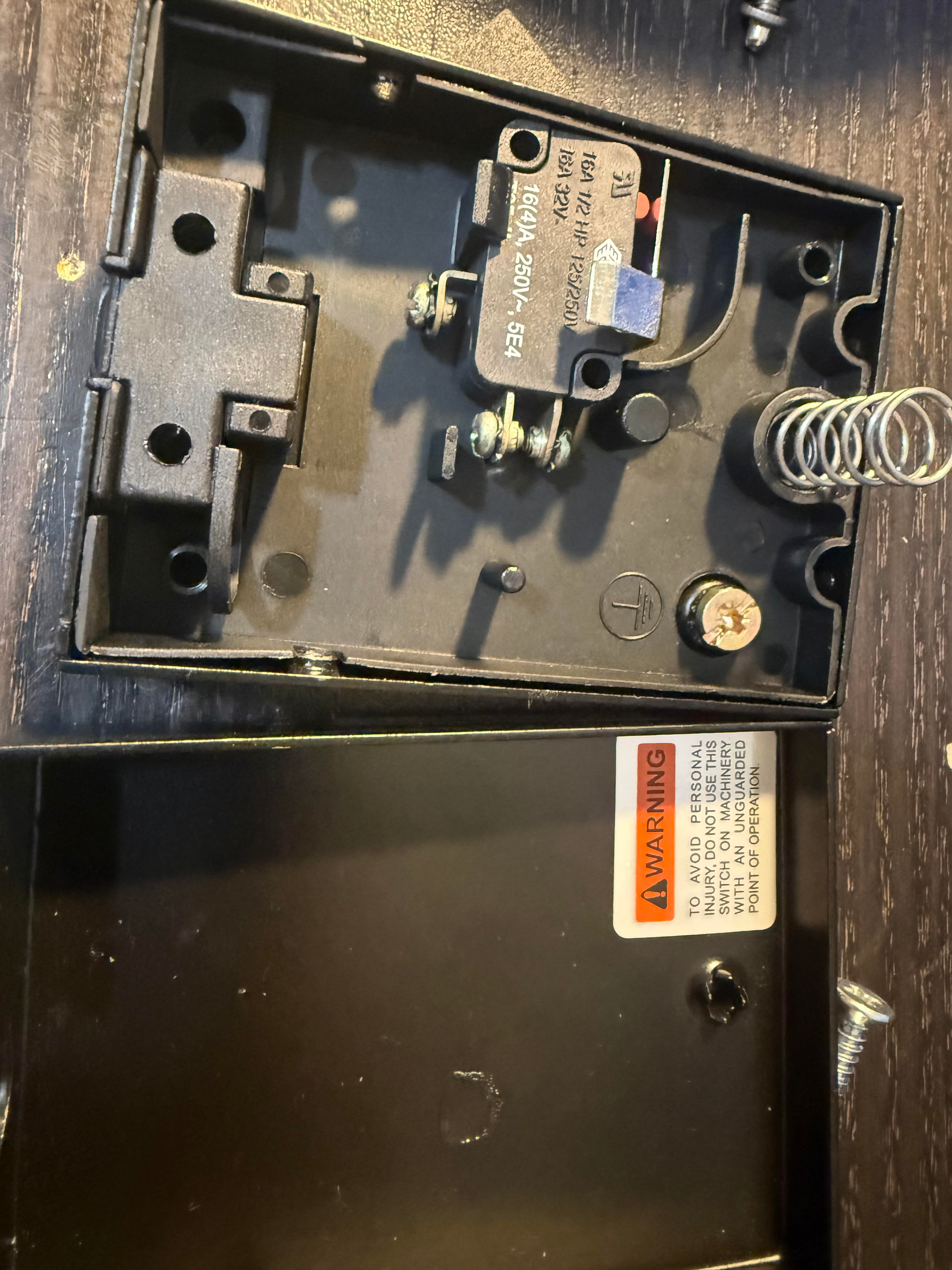
Today I removed the transformer from the microwave and wired together the foot switch.
Today at work during my lunch break I:
- Hacksawed off one side of the secondary
- Drilled holes into the newly flat copper wire brick that filled up the secondary window area
- Used a flathead screwdriver and rubber mallet to carefully pry the insulating paper off of the sides of the window
- Used the same screwdriver and rubber mallet to push the remaining secondary copper wire and metal laminated shunts through the window
- Cleaned up the inside of the winding window
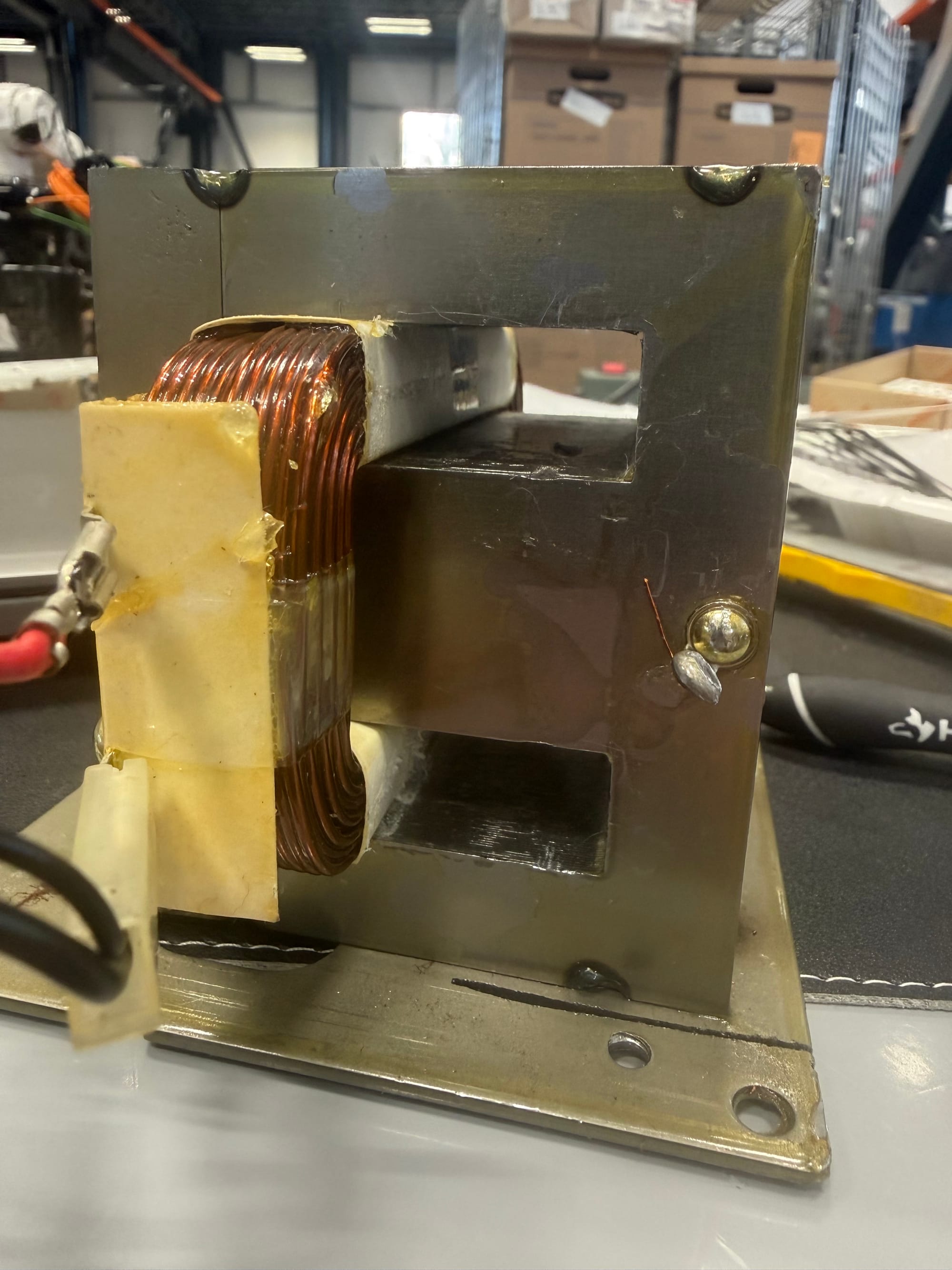
And then at home I:
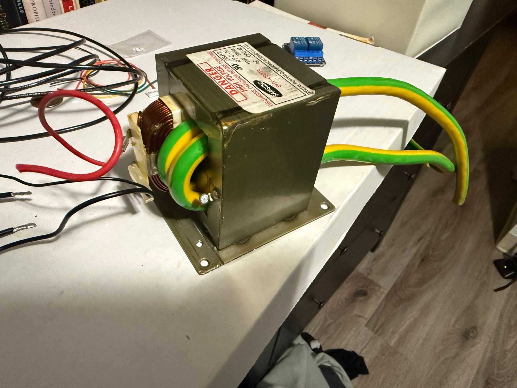
- Pushed 2 turns of 2AWG insulated copper wire through the secondary winding window
Next up is to cut the excess 2AWG wire, crimp and file down the 2 copper lugs to points, create the 555 timer pulse circuit, create the relay circuit, and splice & connect the extension cord to the primary.
JK!! I did a bit of research based on some concerns about the leakage inductance and using a switching relay, and it turns out my concerns were well-founded. The leakage inductance of the transformer will indeed cause high-voltage arcing across the relay when switched off suddenly, interrupting the current. Thus I either need to consider a new control system, over-rate the current and voltage requirement for my relay/switch, use another method of pulsing current, or accept the risks and just use a snubber.
After some research, the TKOR video that I got inspiration from isn't technically a spot welder, and more a metal melter, and so I think the intended operation for that device and mine are somewhat different. Mine wants higher current for a shorter duration to weld nickel together, which is more likely to trip my wall breaker, while Grant's design is intended for lower current for a longer duration to weld steel together. Grant is also likely using a higher current-rating garage socket than I, and thus I need to reconsider my approach.
Out of the previous options, I think I will use a new system based on this Instructable that covers the same project I'm doing but in further detail and considering the downsides and protection that I will need. Because I have all of the components except the spot welding controller, that is all I need to buy. Unfortunately I will have to spend money for this, but it shouldn't be too much for a spot welder and/or metal melter I intend to use often.
Parts required:
- Small AC transformer
- Spot welding controller board
While I do need to buy the spot welding control board, I can just salvage a small 120VAC input, 9VAC output 60Hz transformer from my boxes of random salvaged components.
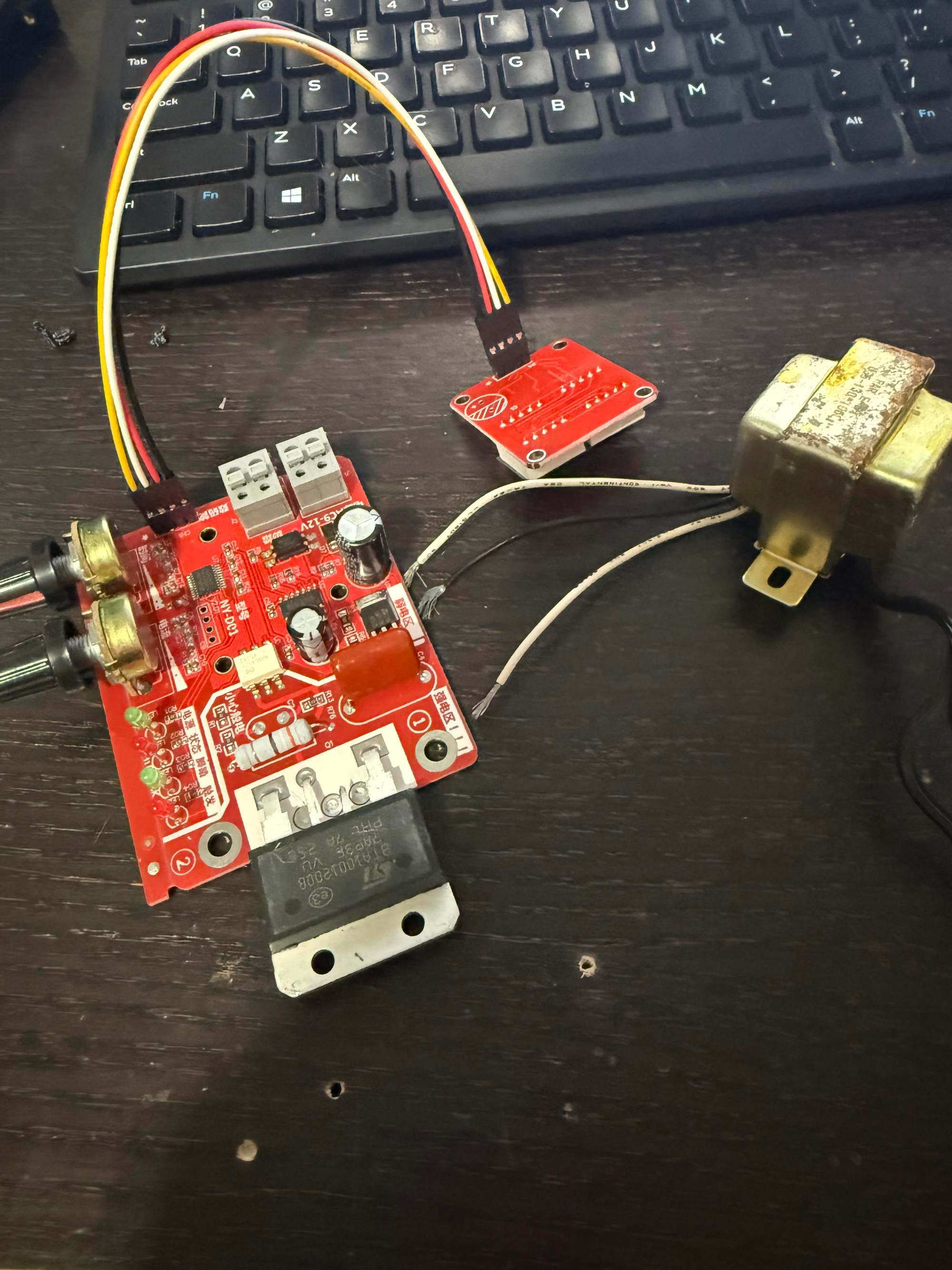
This is the control board I bought. Now I'm planning to create an enclosure for the entire thing in SolidWorks to make it look pretty and mechanically robust.
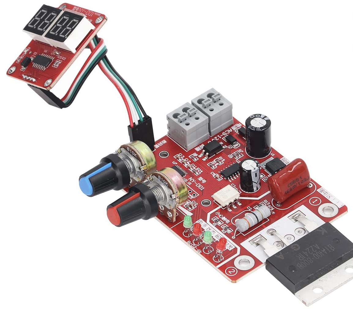
Since I don't know the exact dimensions and mounting holes for the PCB and the display yet, I'll wait for it to arrive before progressing on this task any further.
The spot welder control board arrived, but I took a nap after work because I messed my sleep schedule up a bit over the weekend. The wiring diagram for the spot welder control board is as below:
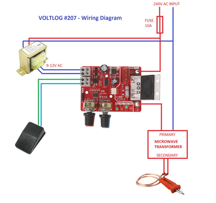
For the 9-12V AC, I'm finding a transformer from my collection that can suffice.

The transformer I found actually produces 12.6VAC on the output across the two live output wires, so I might not use that one and try and find another. I do have another but it's labeled 0-15V output with 3 wires and neither 15 nor 7.5 would work.
I unfortunately only have 3x18AWG AC cables at home, which sucks because 14AWG is the ideal, but if the only thing at risk is temperature, and I'm running at short durations, I think things will be okay.
I don't have a ferrule crimper at home unfortunately, forgot to put it in my tool bag from work. I'll just use my molex crimper instead.
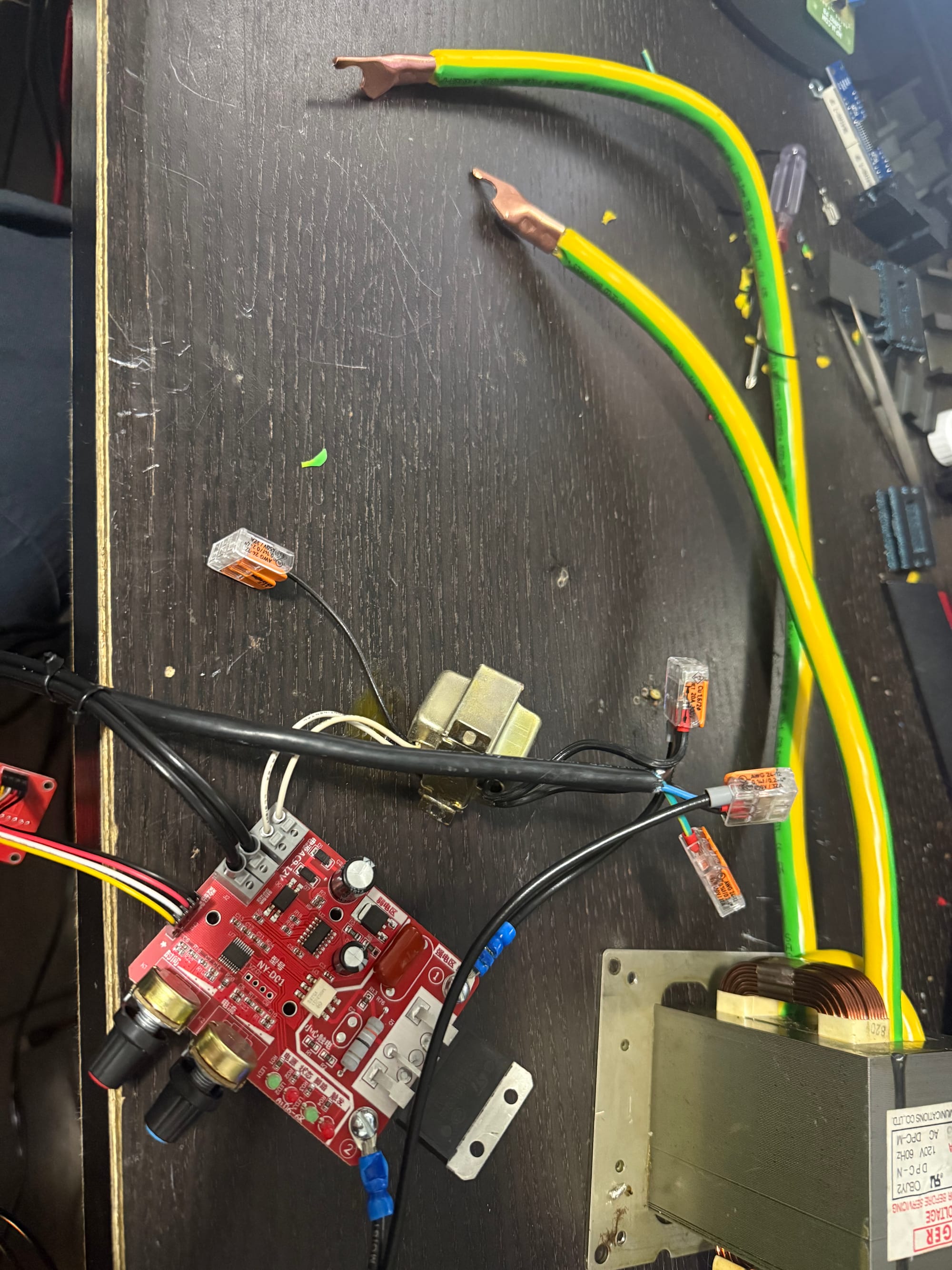
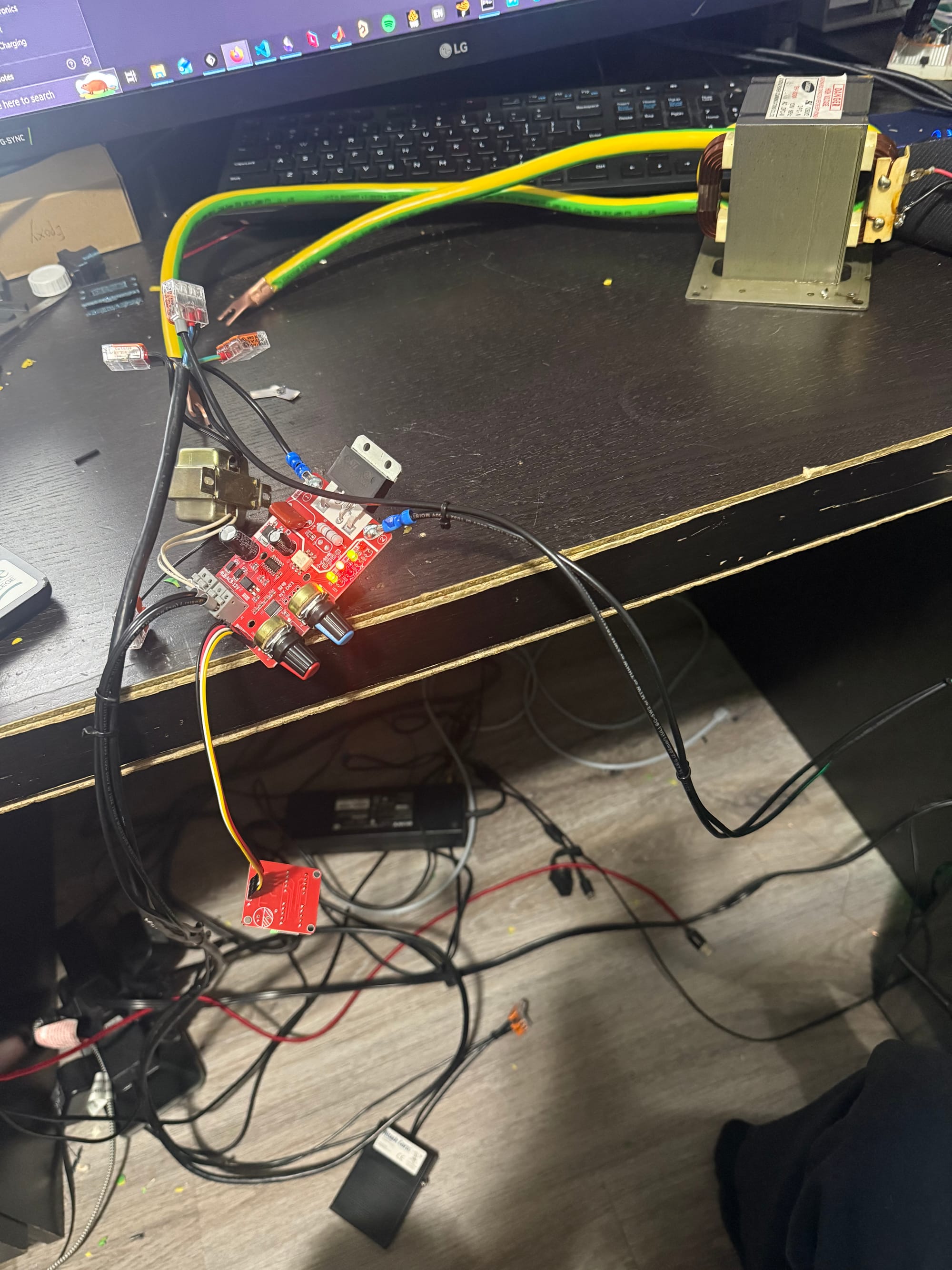
After a while, I got the spot welder to totally work!!!!!!!! All I needed to do was wire up the PCB I bought, zip tie and Wago the cables and wires to make sure everything was accounted for and not touching something else, and it all went swimmingly!!
Batteries welded in 10S config!
Now I'm going to 3D print this enclosure for essentially the same spot welder design from online to save me some time putting everything together and making a nice safe enclosure for it (since I accidentally shocked myself with mains voltage when the control board fell on me during welding...whoops).
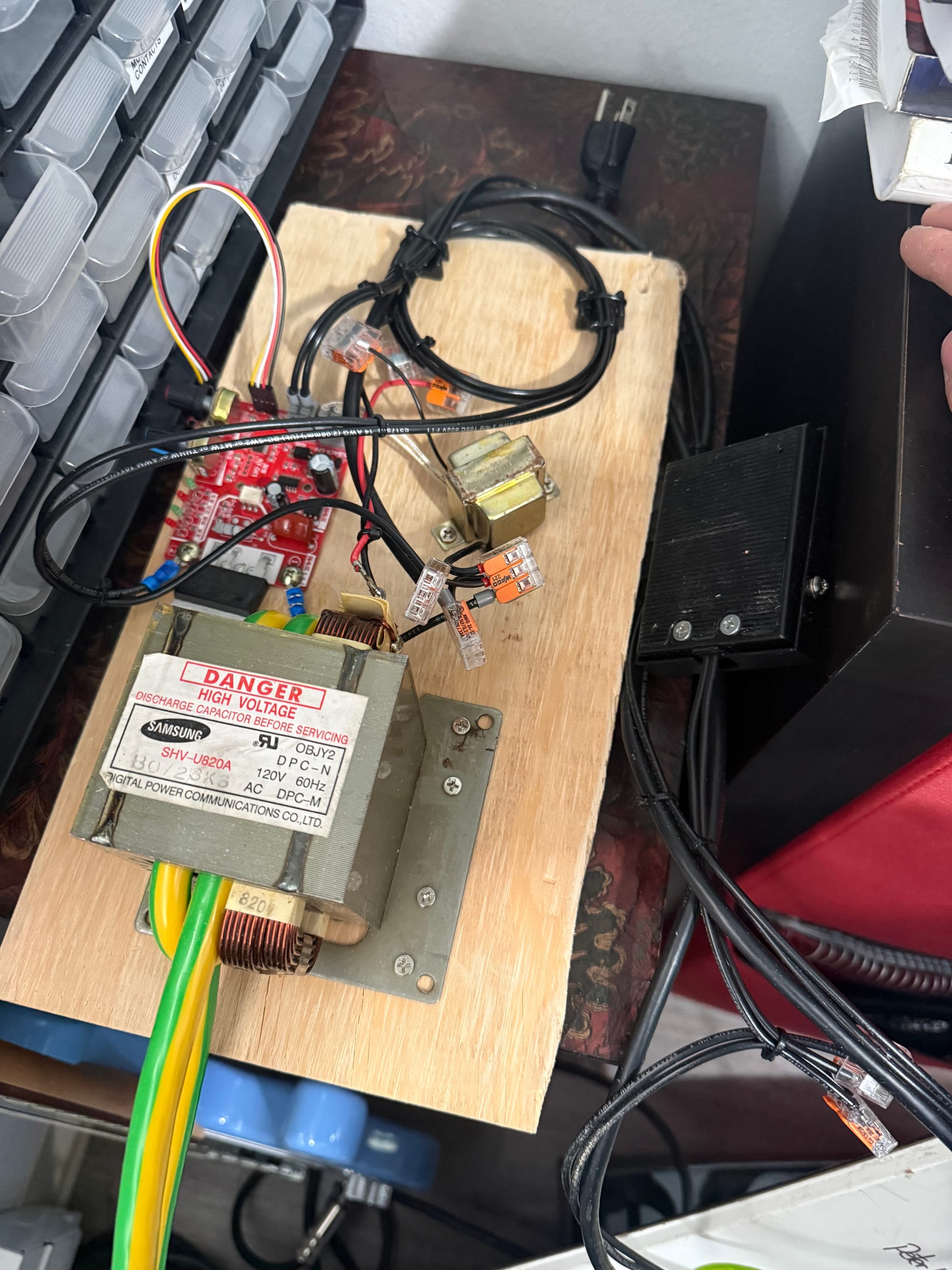
The enclosure didn't end up fitting all my components especially because of the stiff 2AWG copper wires I chose, so instead I bought a wooden board from Home Depot and screwed the pieces and cables directly to the board. Very jank but it works and now just has the foot pedal and power cord extending off from the main body. Creating a full wooden box would have taken a lot more effort and time that I don't really have time for right now.
Improvements
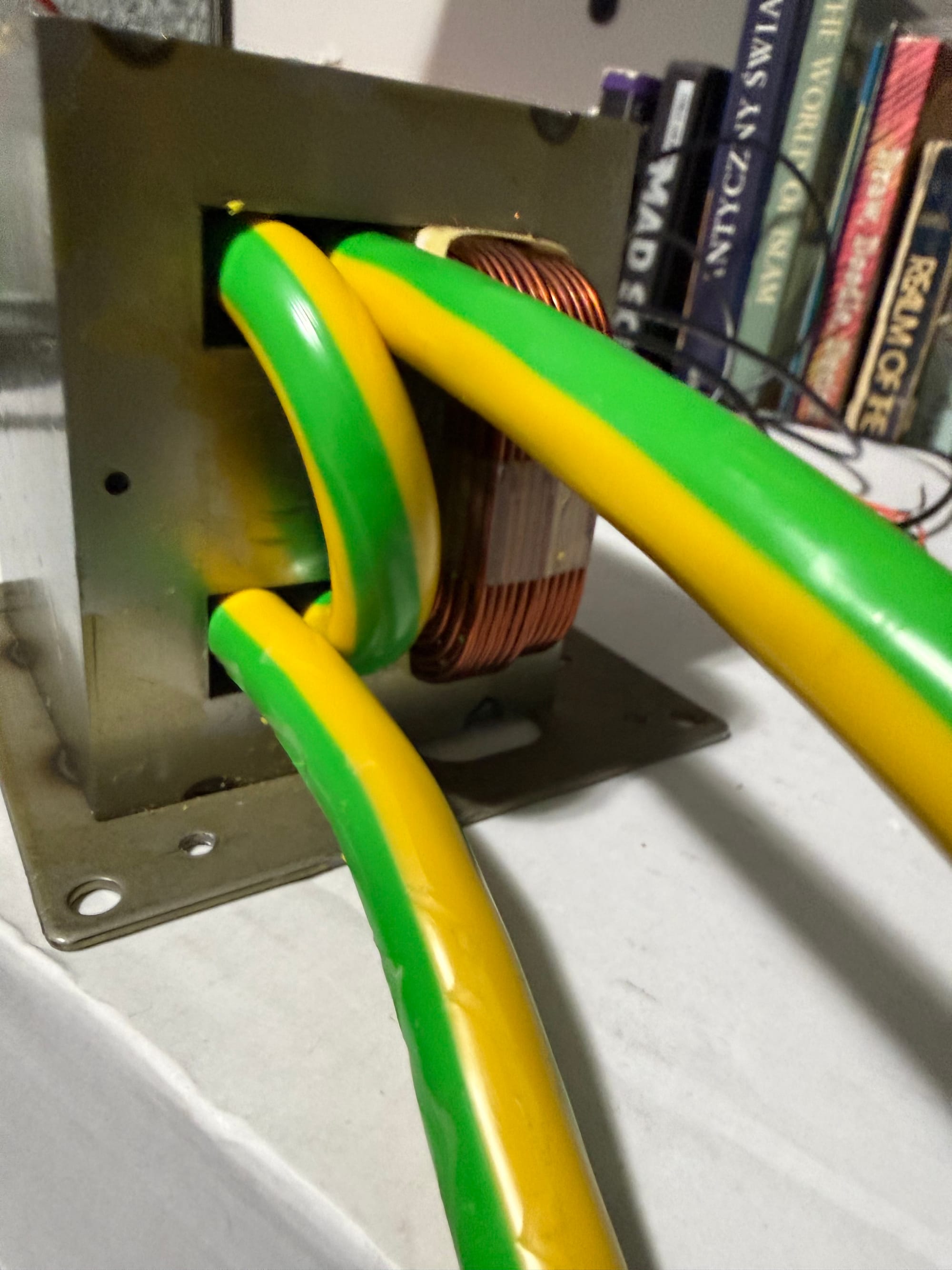
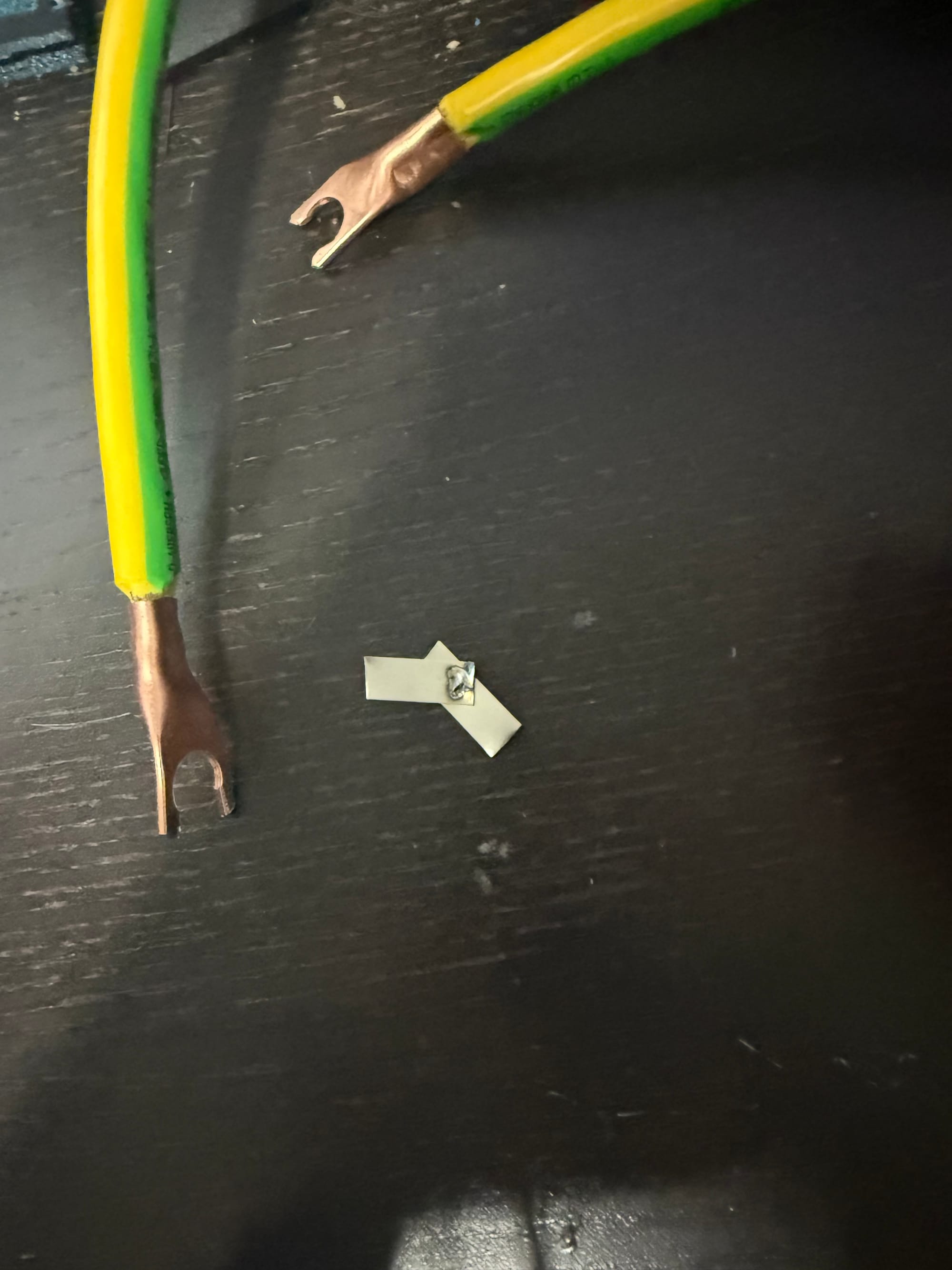
After a bunch of uses of this spot welder, the stiff 2AWG wires were very unwieldy, so I decided to purchase proper, flexible, 2AWG welding cable and use those instead. Here is the result:
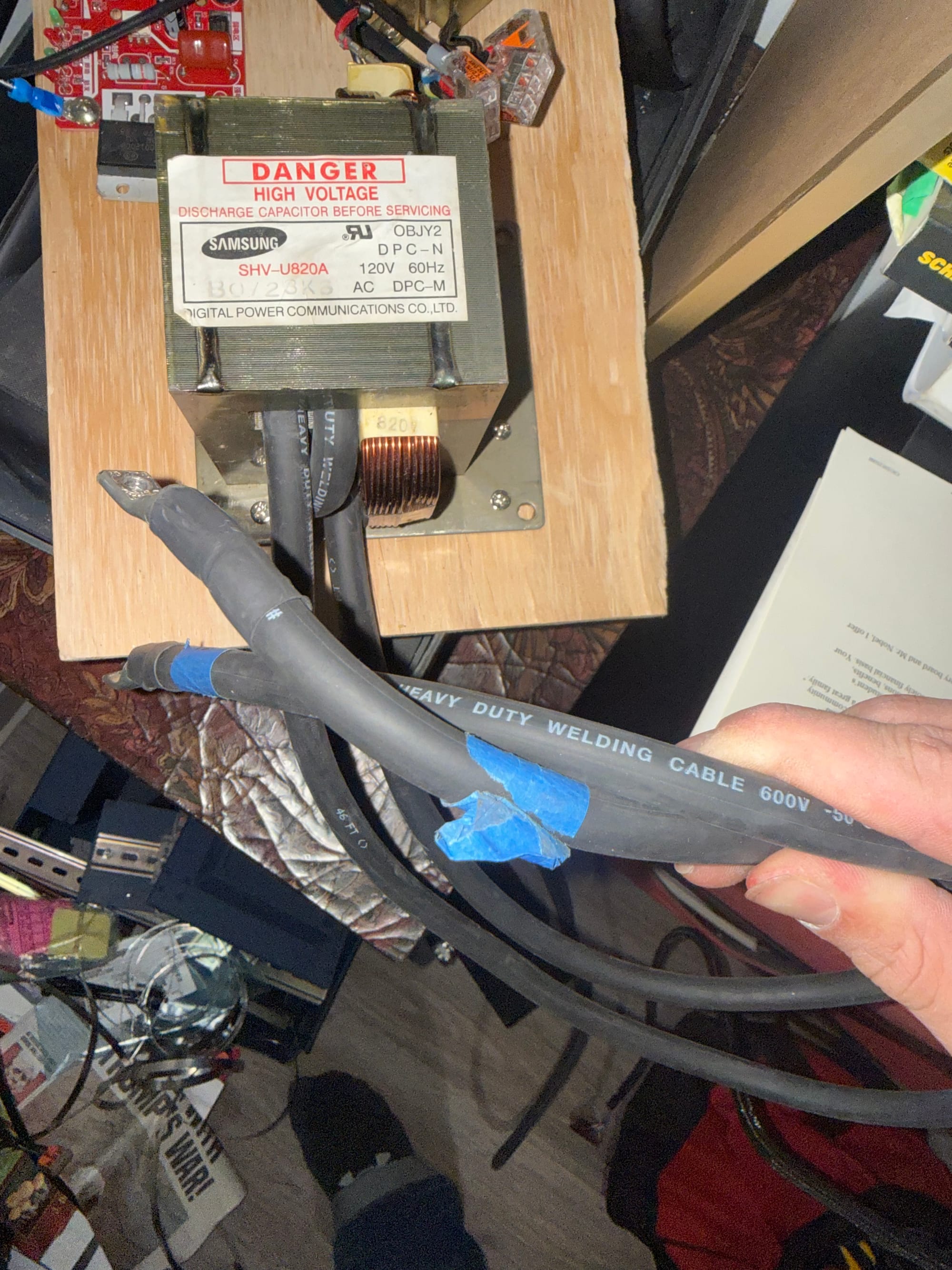
And the lugs and heat shrink on the ends also add a better grip and higher-current tip to discharge through!