HV Power Supply: Resonant Tank and Transformers
With the 200V H-Bridge output at 7kHz, I'll need a resonant tank to filter out the harmonics and a transformer or series of transformers to step up that AC fundamental voltage to 40kV peak-to-peak.
Transformers
After some deliberation, I eventually chose the simple route forward with the HV transformers (where I could either make my own custom transformers or buy somewhat sub-par and non-optimized pre-made ones) due to the advice of a former lab peer that I should build first and optimize later. He recommended I purchase these transformers from Ebay. Because one of them is only rated for 30kV and 200W continuous power, I'll use a parallel-input series-output configuration with 2 transformers to add the secondary voltages (max 60kV) and share the input current (thus max 400W continuous).
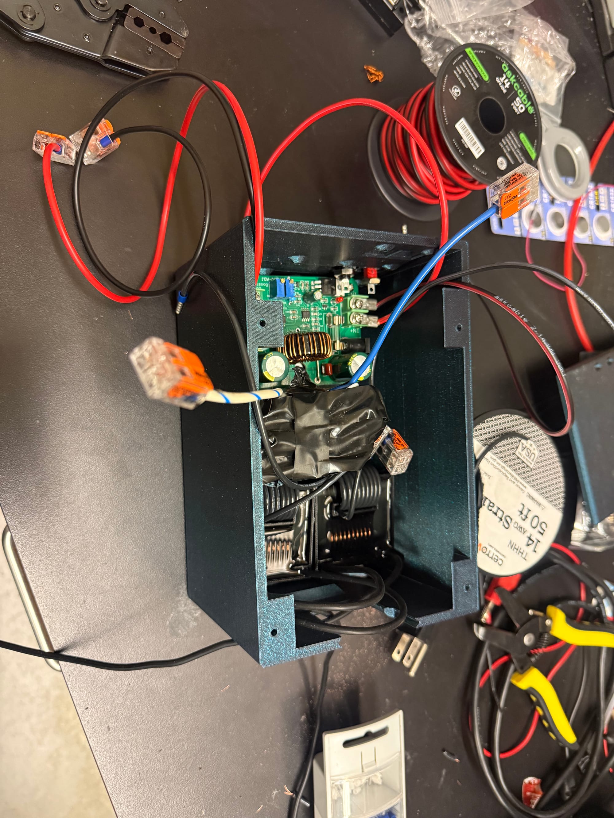
I wound 14AWG wire on each of the primaries, resulting in a 1:120 turn ratio on each transformer, and a 1:240 turn ratio when in parallel-input, series-output configuration. The connected battery, boost converter, and transformers can be seen below: (H-Bridge, AC rectifier, and resonant tank are missing)
Resonant Tank
(Measured LCR values are measured with the DE-5000 LCR meter)
For an applied bipolar square wave at 200V peak-to-peak and a maximum current of ~1A at 7kHz, I need to think about: the resonant filter requirements to create a sinusoid with as few harmonics as possible, the current, voltage, and ripple ratings of my reactive components, and the parasitic capacitances and inductances of my transformer(s) (leakage inductance, inter-winding, inter-turn capacitances) and DBD + Rectifier->Corona load (since they are very capacitive).
Since we don't have access to a testbed for the SDBD or Corona loads yet, I will specify the power supply resonant tank initially assuming some equivalent output capacitance and output resistance, and tuning the self-resonant frequency to \(>5\times f_{sw}\), so it doesn't overlap with switching harmonics and cause ringing.
To constrain the 2-variable resonant frequency equation \(f_{res} = \frac{1}{2\pi \sqrt{L_r C_r}}\), I measured the transformer leakage inductances to be 11.98uH and 12.04uH, which gives 6.01uH equivalent series inductance for the parallel primary windings. This will be considered the minimum bound for resonant inductance.
The transformer secondary winding capacitances are 275pF and 275pF, which when put in series produces a total of 137.5pF in parallel with the load.
If I use a rough estimate of the AC rectifier and SDBD load capacitance across the output leads, I get the following:
AC rectifier: The junction capacitances of the diodes (When measuring the parallel capacitance of the DD1600, they read an average of 3.0pF each) are taken into account for the 4-diode long full-bridge rectifier legs, along with their parallel capacitor (~10pF, to be purchased) and parallel resistor. The corona discharge load capacitance will be estimated as negligible for now. Thus a 24pF equivalent capacitance to the corona load is estimated.
SDBD load capacitance: From my project manager, an upper estimate of 500pF can be estimated for the SDBD load capacitance. (We don't have a Q-V plot of the SDBD actuator measured yet, so this capacitance is unknown for now).
This results in a parallel secondary winding capacitance of 137.5pF and load secondary capacitance of 24pF+500pF=524pF. At 7kHz this results in an AC impedance of \(Z_{load} = \frac{1}{2\pi f C_{load}}=\frac{1}{2\pi 7000 524e-12} = 43.4[k\Omega]\) and \(Z_{winding} = \frac{1}{2\pi f C_{winding}}=\frac{1}{2\pi 7000 137.5e-12} = 165.4[k\Omega]\). The total equivalent secondary capacitance is 524pF+137.5pF=661.5pF, so the combined AC impedance is \(Z_{total} = \frac{1}{2\pi f C_{load}+C_{winding}}=\frac{1}{2\pi 7000 661.5e-12} = 34.4[k\Omega]\). With applied voltage at \(V_{RMS}=\frac{V_{peak-to-peak}}{2\sqrt{2}} = \frac{40,000[kV,peak-to-peak]}{2\sqrt{2}}=14.14[kV,RMS]\), the circulating current sloshing through the secondary is \(\frac{14.14[kV]}{34.4[k\Omega]}=411[mA,RMS]\), whose reactive power is \(14.14[kV,RMS]\times 411[mA,RMS] = 5.8[kVAR]\). The actual loss from this depends on the loss tangent \(\delta\), which I'll have to measure.
Regardless, the total reflected load to the primary depends on the turn ratio of the transformers (since their outputs are in series) of 240 sec to pri. The total equivalent secondary capacitance is 524pF+137.5pF=661.5pF, meaning
\(Z_s = Z_p \times n^2\)
\(Z_p = 661.5e-12[F] \times (240)2 = 38[uF]\)
is the primary equivalent capacitance, and what I should consider as my capacitive load to the resonant tank. That 441[mA] of secondary current thus is reflected to the primary and becomes \(I_p = 240\times 0.411 = 98.6[A,RMS]\) at 7[kHz] which is far beyond my design goal of 1[A,RMS]. This means the reactive impedance is too low, and circulating current will dominate and break my system. The RC low-pass filter 3dB bandwidth is attempting to filter out too many frequencies, and a large amount of current is sent through the capacitors since their impedance is too low to those frequencies.
If adding the leakage inductance of \(6.01[\mu H]\), impedance to high frequencies is increased, however the capacitance and leakage inductance resonant frequency ends up close to the switching frequency and actually raises the circulating current:
\(f_{res} = \frac{1}{2\pi \sqrt{L_r C_r}}\)
\(f_{res} = \frac{1}{2\pi \sqrt{6.01e-6 \times 38.1e-6}}[Hz] = 10.5[kHz]\)
\(X_L=2\pi(7000)(6.01e-6)=0.264[\Omega]\)
\(X_C=\frac{1}{2\pi(7000)(38.1e-6)} = 0.597[\Omega]\)
\(X_{net}=X_L-X_C = -0.333[\Omega]\)
To limit this in a lossless fashion, I need to increase the series impedance of the tank. I could do this by decreasing the parallel capacitance (cannot, as those components are fixed) or increasing the series inductance. Since I want 1[A,RMS] of primary current to be supplied to the load as output power, I ideally want the circulating current to be as low as possible, and thus need a supplemental series inductor. I can wind this myself with 21AWG or 18AWG magnet wire that I have, and the E38 or E58 ferrite cores and bobbins I have.
Because the supplemental series inductor will lower the resonant frequency in turn, I need to supply additional SERIES capacitance to the tank so that the resonant frequency remains below 7[kHz] and I sustain ZVS (soft-switching). I already purchased 2 \(650VAC 1.2[\mu F]\) PP capacitors for the resonant tank, so I will use those and calculate the required series inductance to limit circulating current to 10% of load current. The measured capacitance of the 1.2uF 1.6kVDC resonant tank film capacitor R75TW4 12050H3J at 5% tolerance was 1218.0nF with an ESR of 0.02ohm.
#continue
- Calculate series inductance