HV Power Supply: Battery and Boost ✅
Battery
The battery specifications for the HV Power Supply are:
- 6S (22.2V nominal)
- >200W minimum output power
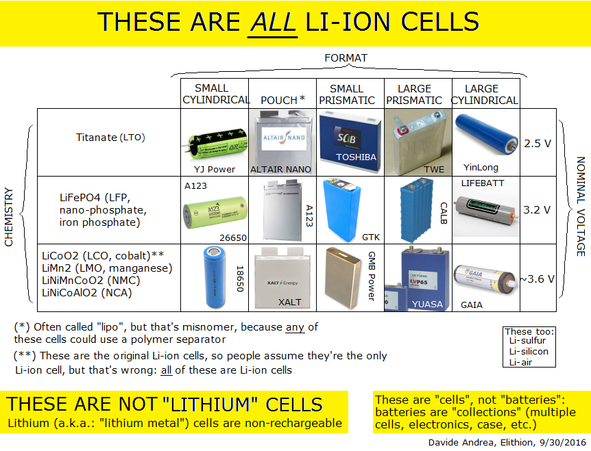
When researching how to create a battery pack, I came across this invaluable Reddit post on batteries. This is where I got most of my battery-related information from. From what I understand, for a basic Li-ion battery pack, I require:
- The cells (obviously)
- Protection circuitry (often included with the BMS, but not always)
- CC-CV charging port/connector to attach a charger to, and the CC/CV charger to charge it that is specified for the amount of series cells I am using
- BMS
- Boost or buck converter on the output to smooth the voltage across the discharge curve
I am planning to use a BMS PCB ordered from Amazon, individual 12A 18650 cells that I already have (thus allowing for \(12 \times 3.0 \times 6 = 216.0[W]\) total at the minimum charge voltage, and \(12 \times 4.2 \times 6 = 302.4[W]\) at the maximum charge voltage), charged by a CC/CV charger also bought from Amazon, nickel strips ordered from Amazon, and spot-welding and soldering all electrical connections and BMS sense wires myself.
Our outcome should be structured something like this diagram for a BMS circuit from MOKOENERGY, where the load in this case is our boost converter:
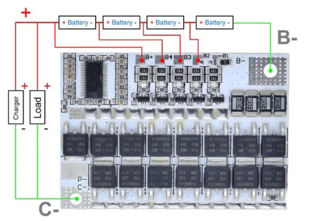
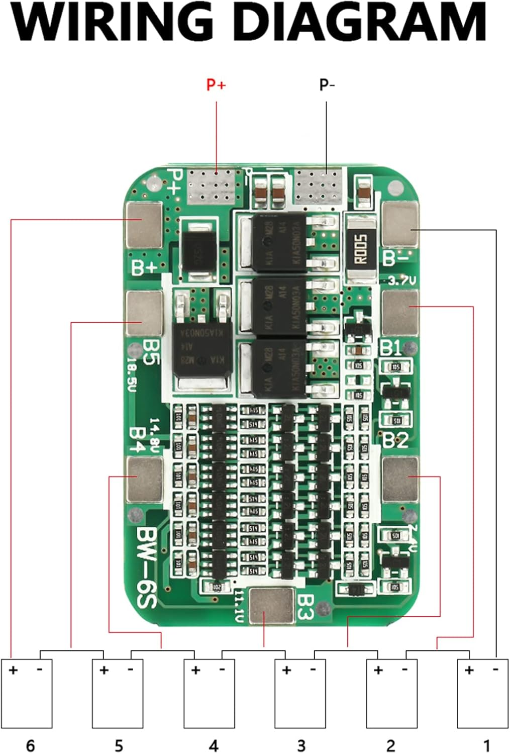
For the BMS, I chose this Amazon 6S BMS, which will be charged via this 6S charger also from Amazon. Both have good reviews and seem reliable. The wiring diagram is as below:
A: Calculates State of Charge (SoC), temperature, and voltage for each cell to prevent overcharging or over-discharging. It also balances the charge between cells by ensuring they are charged and discharged evenly, to maximize lifespan. Safety features such as detecting thermal runaway, overcharging, and over-discharging are also implemented. Communication about status is also sent to other systems and devices.
A: Protected have little circuits that make sure the voltage doesn't get too high or too low, and prevents damage from short circuits. They add about 3-4mm to the cell length.
- The Terminal Voltage is not a reliable indication of SoC, because it is also drops at high discharge current, and is affected by temperature.
- For 21700 and 18650 cells, do NOT solder them, as the separator and electrolyte will be destroyed with the prolonged heat. Ideally, these cells should be spot welded, but a cell holder might be okay for minimal vibration.
I chose these nickel strips because they have the best reviews and are the most widely sold on Amazon. Their electrical characteristics and details are given below:
Notes on Power Strip Connections:
Nickel and Copper are both used for the power strips for battery packs. Copper is ~4x more conductive than nickel, but this just means that a higher mass of nickel will need to be used than copper. Copper is also extremely hard to spot weld as opposed to nickel for the same reason (high thermal and electrical conductivity), so nickel is most commonly used for battery pack connections.
An additional option as opposed to just nickel or copper is using nickel simply for the welding part (as the high current passes through the surface of the nickel and heats up very quickly, welding the nickel AND the copper layer underneath to the cell) and using a layer of 0.1mm copper underneath, directly touching the cell, as the main power conductor, in order to minimize weight and maximize conductivity.
| Nickel Size (thickness × width) | Approx. Max Continuous Current |
|---|---|
| 0.10 mm × 7–8 mm | ~8–10 A |
| 0.15 mm × 7–8 mm | ~12–15 A |
| 0.15 mm × 10 mm | ~15–20 A |
| 0.20 mm × 7–8 mm | ~20–25 A |
| 0.20 mm × 10 mm | ~30–40 A |
| 0.30 mm × 8–10 mm | ~40–60 A (requires a strong spot welder) |
| Source: Spot Welding Copper Strips on 18650/21700 Cells - Cell Saviors and What Nickel Strip Size You Need for DIY Battery Building (Thickness & Width Guide) – RenewSpark |

A: Metal contacts are not recommended for high current applications for Li-Ion cells. Spot welded contacts are much more reliable mechanically, give lower resistance, space efficient, cheap, and give more metal-to-metal direct contact than springs which may only touch a line or single point on the Li-Ion cell. For low current, they might do the job, but are still not ideal.
I created two batteries via my spot welder, 3D-printed cell spacers, banana plug output, soldered balancing wires (scratching the nickel before soldering to ensure actual adhesion), and hot-glued BMS onto the side of the pack. When charging at 2A everything appears to be in order!
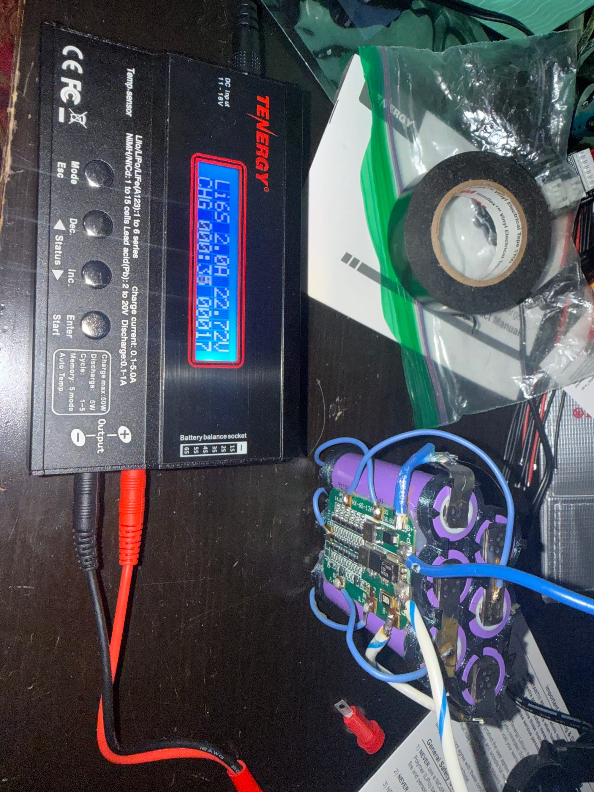
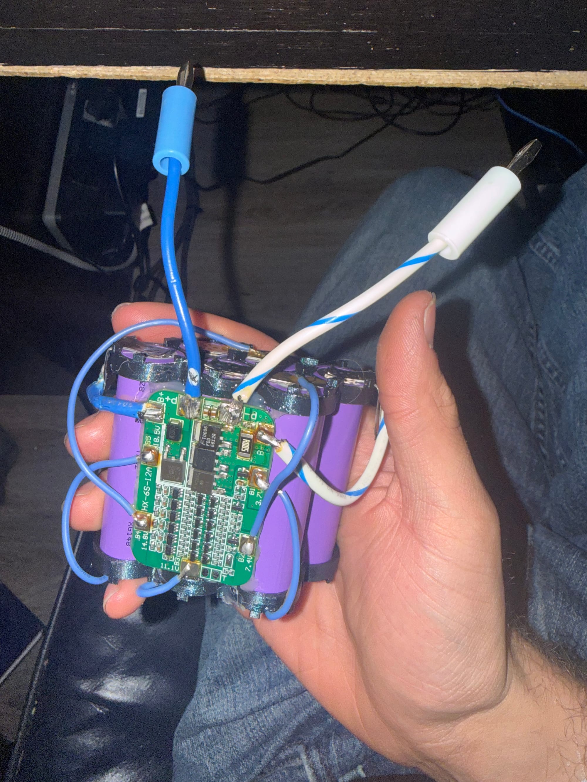
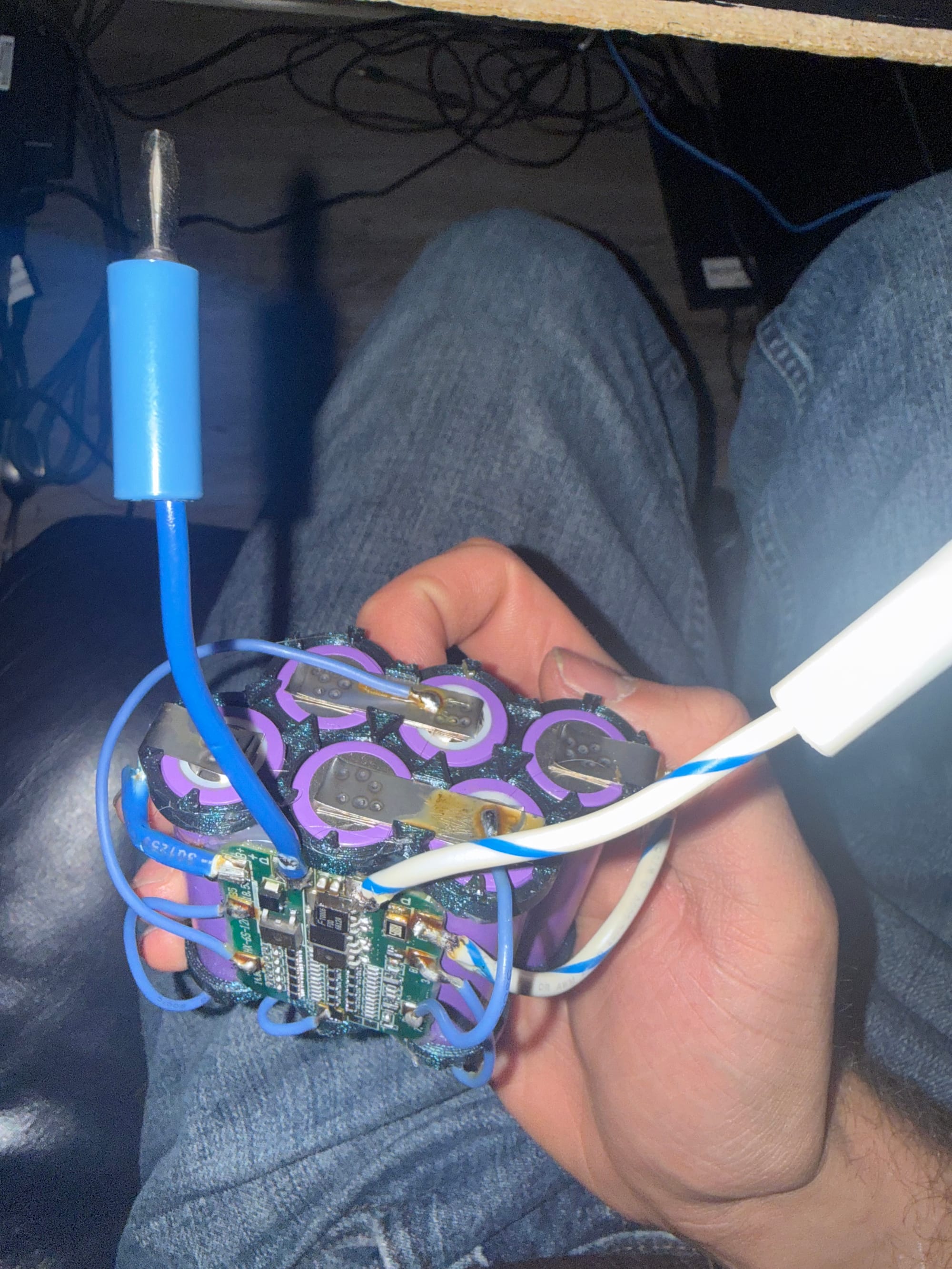
And when reading with a multimeter, it says 25.2V at full charge as expected! I added 3 layers of spot-welded 0.2x8mm nickel strips because each one only handles 6.5A continuous, and I want to use these for their full potential 12A (so now it's only limited by the BMS). Batteries complete!
Boost
Because my HV power supply benefits from a high DC voltage to limit the turn ratio of my transformers to reasonable numbers (since a 36.0V bipolar square wave to 40kV peak-to-peak sine requires about a 1:873 turn ratio, calculated from the ratio of the fundamental of the square wave to 40,000) I am going to use a boost converter between the battery and the H-Bridge. This also allows smoothing of the battery voltage to a consistent value, instead of falling significantly as it becomes discharged.
For this aim I am buying a premade boost converter specified for an input voltage range including 18.0-25.2V and an output voltage as high as possible.
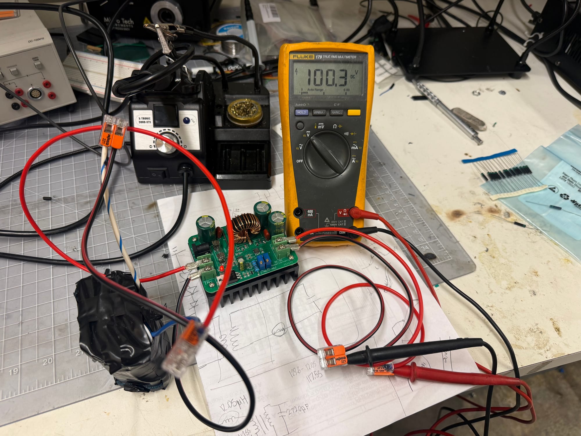
This Amazon listing seems to satisfy those requirements exactly, and surpass my 200W requirement by 400W extra, so I'll buy one of these as a robust option for the project. All this will require is for me to crimp a ferrule onto the output leads of my battery and tune the output voltage and current via the potentiometer to fit my needs. I'm assuming the current potentiometer is for current limiting and not constant current, but I'll test to confirm.

After applying a variety of loads and just testing open-circuit voltage, at least at output power less than 10W, the boost actually seems stable at even 100V! This is great! I wish I had an electronic load or high power resistor to test higher power outputs to see if the output voltage droops and by how much, but maybe I'll just have to test with the real thing once the full power supply is completed instead.
The current potentiometer also seems to change current limit and not constant current level, as I expected.