HV Power Supply: AC-DC Rectifier
Because the HV AC output voltage is already 50kV from the transformer and the desired DC and AC output voltages for the UW power supply are 50kV, I have two options for the DC output voltage for the same power supply:
- I can simply use a rectifier to turn the 50kV peak-to-peak into \(V_{dc}=0.637V_{max}-2V_{f}=0.637 \cdot 25kV-2V_{f}\) from the full-bridge rectifier AC to DC conversion relation in this article, with voltage ripple \(V_{ripple} = \frac{I_{dc}}{2fC}\). I can use high-voltage diodes like this assuming the reverse recovery time is short enough to allow 2kHz rectification.
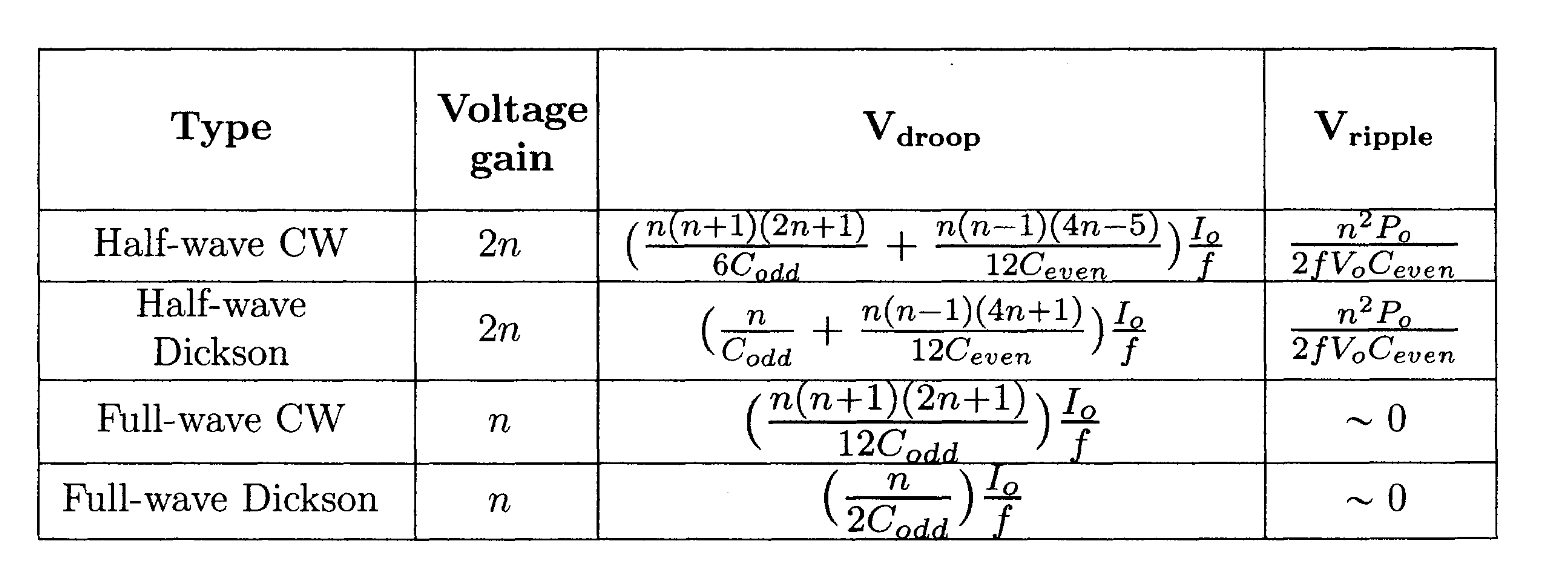
- I could also use a transformer seperate from the series-output transformer stack and simply manufacture a lower turn ratio for that transformer so the output voltage is lower, then use a few stages of a full-wave CW multiplier to achieve ~0 voltage ripple through the equations for voltage multiplier gain, droop, and ripple per topology given by the following figure. This would add more weight, however it would also likely produce a cleaner and more consistent HV DC voltage for the EHD thruster.
For this initial prototype, I'm purchasing 32 of the DD1600 16kV 20mA diodes from Digikey to use as a high-voltage rectifier. This will reflect less capacitance to the primary than a CW multiplier, and be more simple and compact than using an additional transformer with a smaller turn ratio.
Importantly, I'll need to put them in series to achieve the maximum DC voltage of 40kV, probably 4 or 5 in series. This means I'll also need balancing resistors in parallel with the diodes, and dV/dt limiting capacitors in parallel with the diodes, following the quote from this HV forum thread:
The usual solution is to put a high-value resistor in parallel with each diode. Select the value of the resistor so that the current through the resistor (when the diodes are reverse-biased) is about 10× the worst-case leakage current of any diode. This means that the reverse voltage that appears across the diodes will not vary by more than about 10%.
Note that this still means that you need some margin in the ratings of diodes. For example, for 600V of peak reverse voltage, you should use four 200-V diodes, not three.
There is another phenomenon that comes into play as well. The diodes will not all "switch off" at the same speed when going from forward bias to reverse bias. Again, the "best" (fastest) diodes will fail first. The solution for this is to also place a capacitor, about 10 to 100 nF, in parallel with each diode. This limits the risetime (dV/dt) of the reverse voltage, allowing all of the diodes to switch before it rises too high."-https://electronics.stackexchange.com/questions/136036/do-serially-connected-diodes-share-equal-reverse-voltage/136038#136038
We have chosen to purchase 22pF and 220Mohm components to place in parallel with each leg of the full-bridge rectifier.
When manufacturing this rectifier, we plan to solder the legs of each through-hole component in corresponding parallel and series configurations, then use potting epoxy under a vacuum to provide thorough arcing protection.