Custom High Voltage Power Supply🟨
This will be a multi-week endeavor taking multiple steps. I will upload them one at a time. The feature image is an updating view of the progress.
This is a great paper I found that covers the goal application and power supply topologies: https://arxiv.org/html/2512.18067v1
The sub-projects within this power supply follow the production of a prototype high-voltage SDBD flow control actuator and DC corona discharge power supply for small UAV applications relevant to my work with the Sensors, Energy, and Automation Laboratory at the University of Washington. Keep in mind while reading that I work 40hr/wk at Electroimpact, so my project time is limited.
Specifications and Project Description
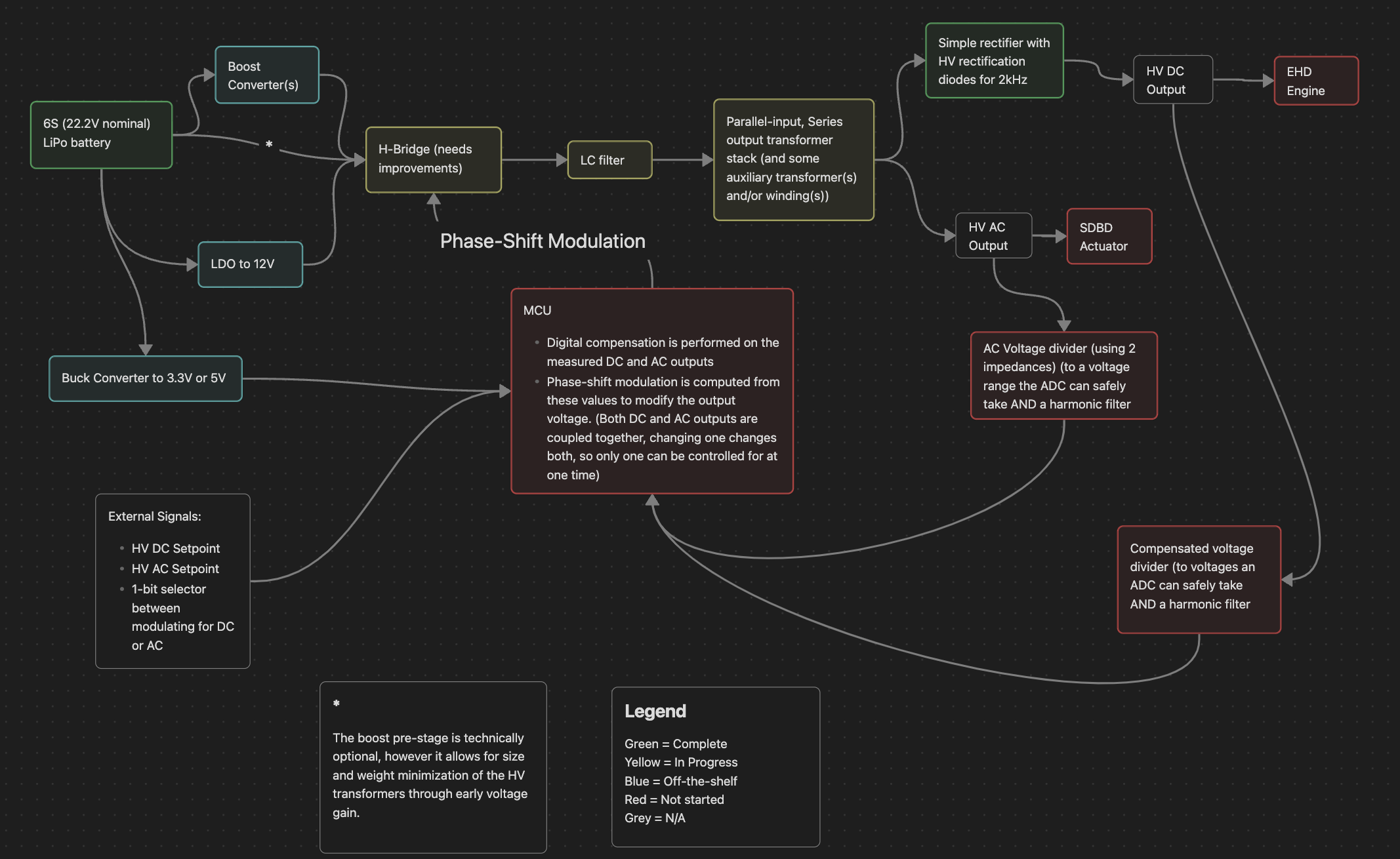
This project aims to convert the power from a 6S Li-ion battery (18-25.2V) to one 40kV DC output for a corona discharge electrohydrodynamic thrust device, and another 40kV peak to peak AC output for a dielectric barrier discharge flow control device.
The output power total for the plane prototype can be estimated at 200W for now, however it is subject to change and we will be oversizing the initial prototype to provide margin and upward scalability if the thrust parameters do not prove adequate during testing.
Compensator and Modulator
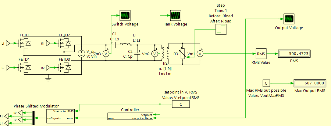
For the control architecture of this HV power supply, I used the advice I received from a Power Electronics PhD student at UW during an ECE research showcase in 2025, which is to make a power supply using a TI C2000 MCU for the control architecture. To simplify the process, I also plan to use a PLECS model because TI C2000 code generation is natively supported. I also currently have a PLECS model of the HV inverter with PID tuned for the digital estimate of my power supply. Obviously in reality my PID coefficients will change, but for a general structure, the closed-loop architecture shown below will be replicated and hopefully function the same, since mine regulates the sinusoidal HV output voltage to the setpoint consistently (between 3 and 10 kV at a fixed frequency):
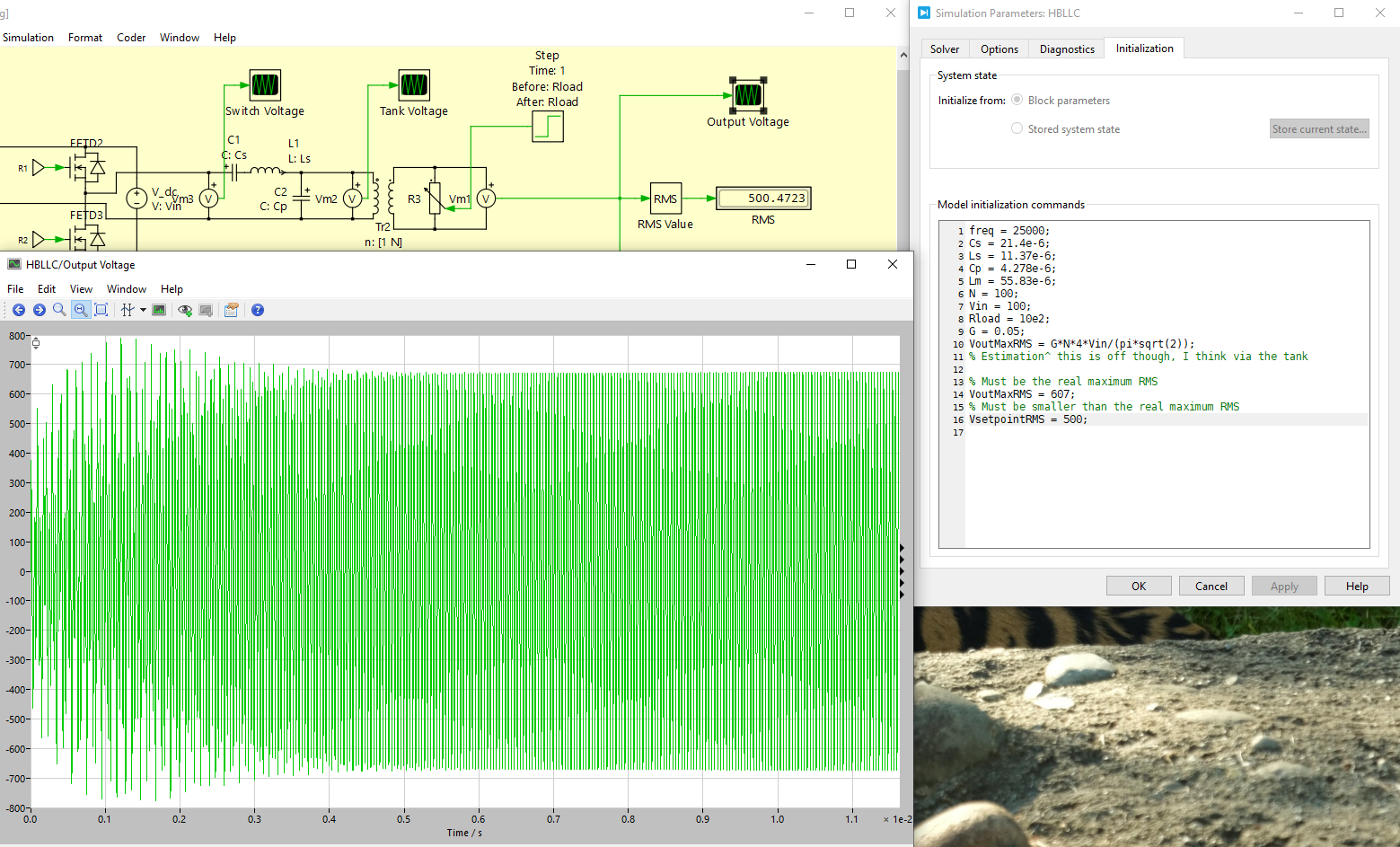
freq = 25000;
Cs = 21.4e-6;
Ls = 11.37e-6;
Cp = 4.278e-6;
Lm = 55.83e-6;
N = 100;
Vin = 100;
Rload = 10e2;
G = 0.05;
VoutMaxRMS = G*N*4*Vin/(pi*sqrt(2));
% Estimation^ this is off though, I think via the tank

% Must be the real maximum RMS
VoutMaxRMS = 607;
% Must be smaller than the real maximum RMS
VsetpointRMS = 500;
MATLAB initialization code for the model
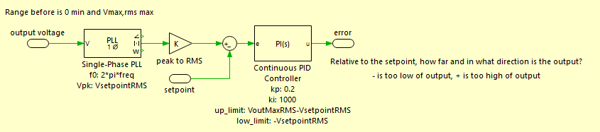
Unfortunately, while this model works well and the control architecture functions as intended, there are a few issues I noted when making it. First though, I will cover the design of this model in detail, and my choices in designing it:
The H-bridge architecture was chosen for its full utilization of both sides of the transformer B-H curve, its doubling of the DC input voltage, its options for gate driver modulation, and generally common usage in DC-AC inversion.
continue...
Issues:
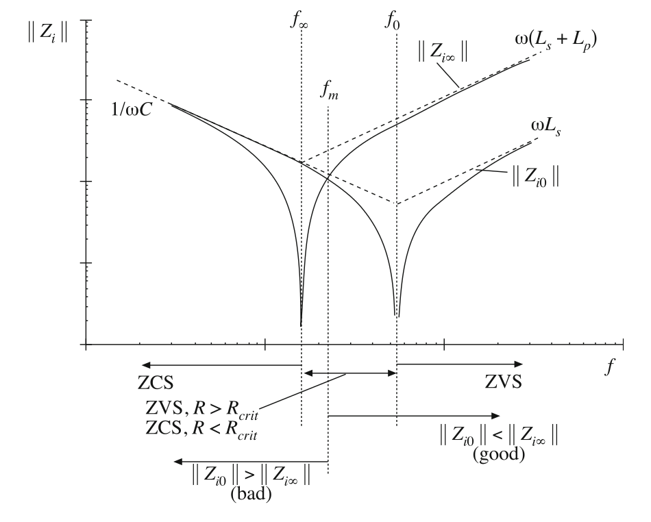
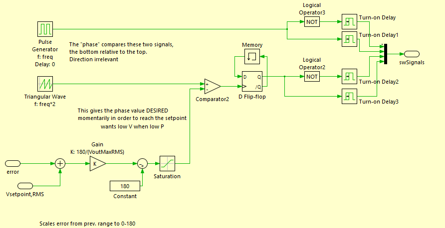
Firstly, I am only utilizing a voltage-mode control loop based on the RMS equivalent output voltage. This is not compensating based on a linear model or estimate of the power stage, but rather is tuned to the RMS setpoint based on a phase-locked-loop (PLL) tracking the output voltage by assuming the output is sinusoidal. This results in relatively slow response, and the fact that there is no current loop means that the inverter is extremely load-dependent, since load impedance changes adjust the efficiency of resonant inverters/converters and can move them out of ZVS if the load resistance is in the wrong region for a given set of resonant frequencies for the LLC tank, which is a quality that non-resonant topologies don't have to deal with. This is shown by the graph of LLC tank input impedance at open-circuit and closed-circuit conditions below: