Coil Winding Machine ✅
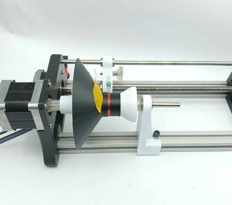
Today I went to the capstone team I am assisting with at UW, and for their magnetism-related project, they needed a way to wind solenoids (coils of wire) easily since their current method caused crossed wires and irregular performance in their application. Inspired by this and the problems I've been having with winding my own transformers and inductors, I got the idea to make an automatic coil winding machine. I looked up DIY designs online, and found this one which looked easy, relatively cheap, high quality, and promising for a variety of uses. Because I expect to be making custom transformers and inductors often, and my capstone team would like one, I decided I'll stick with it, and slightly branch off of this project to pursue building this.
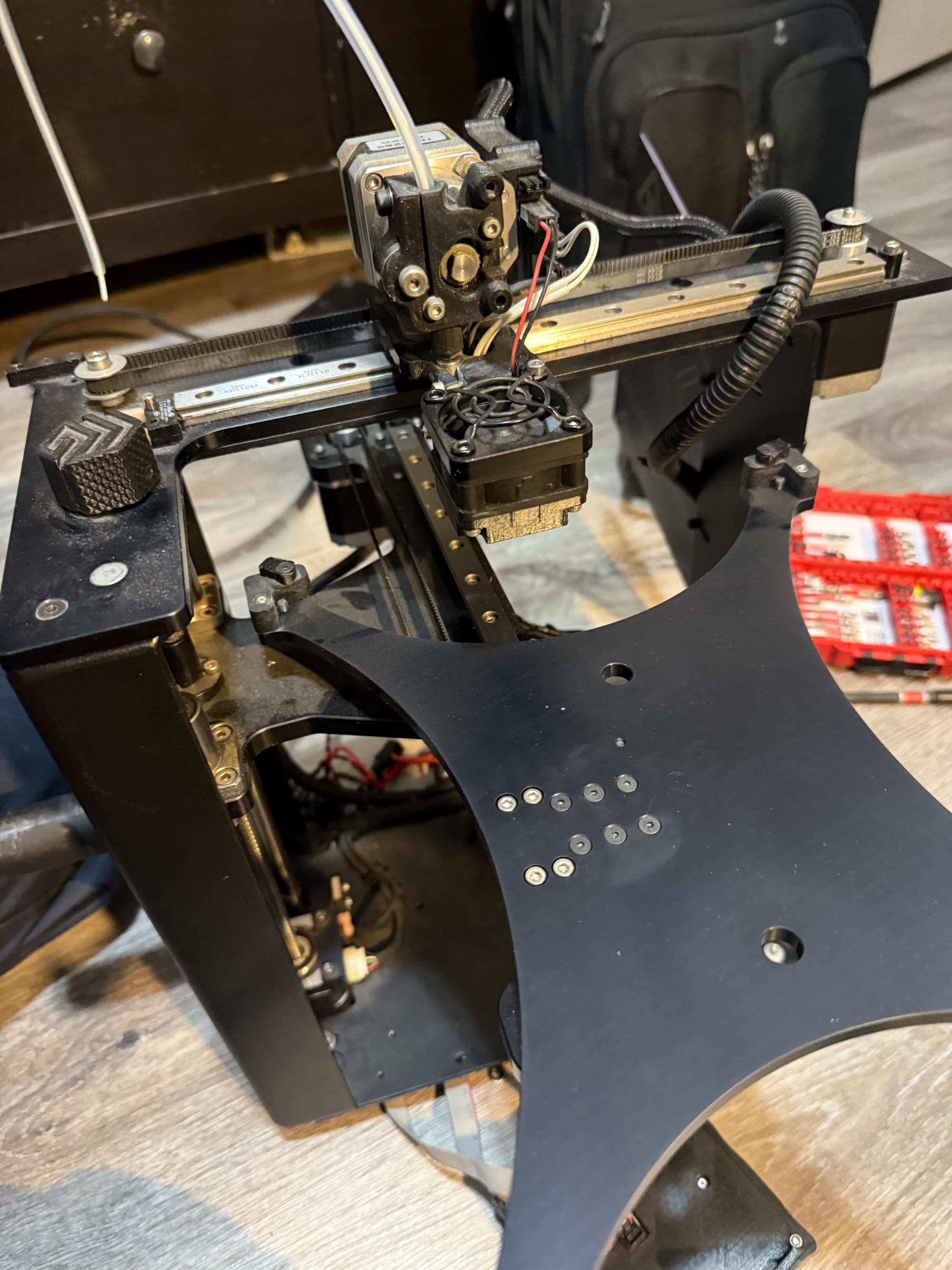
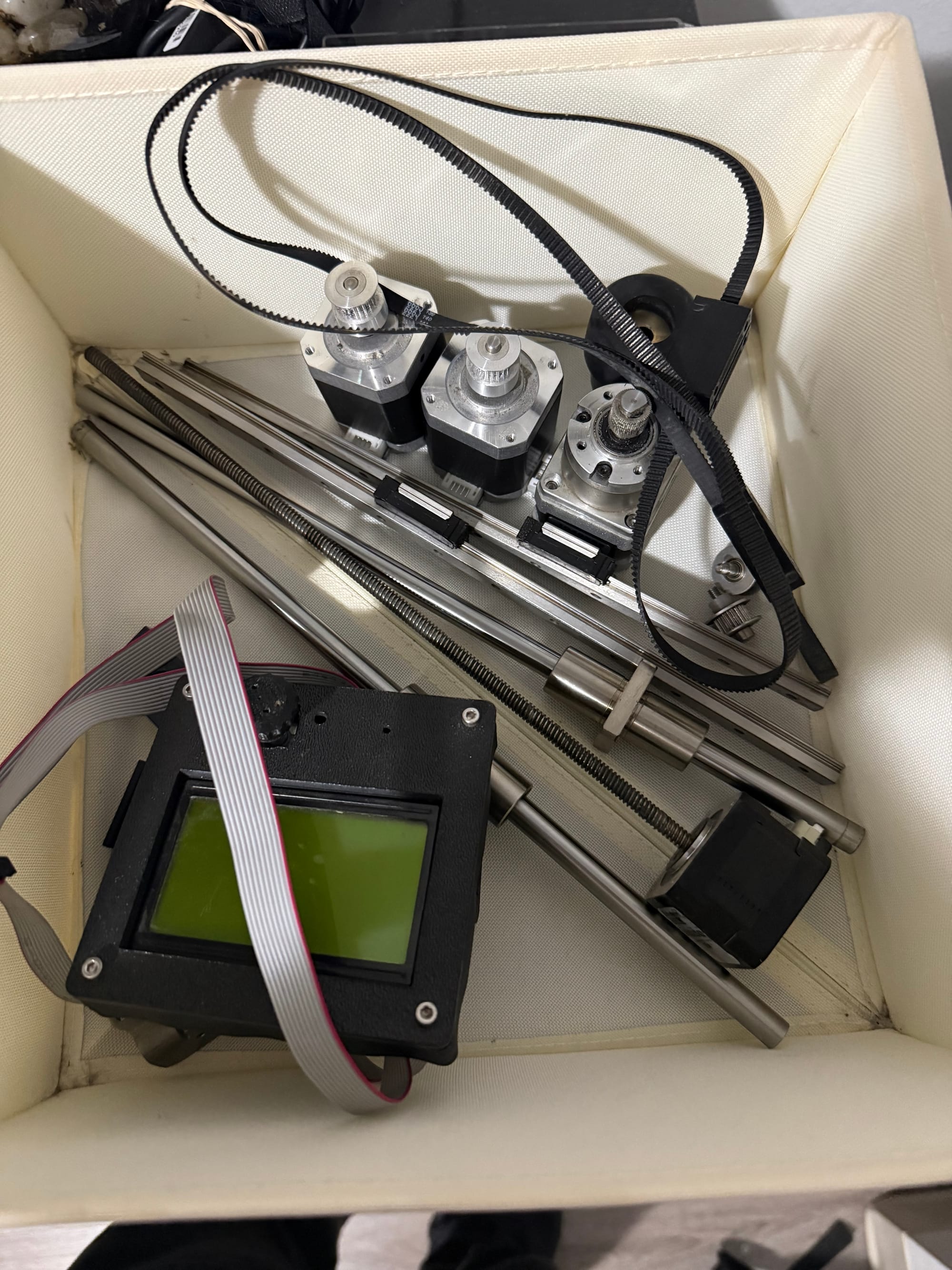
To make this, I would likely need to buy a lot of components, and it would cost upwards of $100-$200 which is obviously unacceptable, so I made my way to Facebook Marketplace while with the capstone team, searched up "3D printer" since the Instructable mentions the components are all essentially just CNC or 3D printer parts, and on my phone found a listing immediately for "Free 3D printer for parts; broken". I was ecstatic, said goodbye to the capstone students, and went to go pick it up. This is what I brought back.
Amazingly, as I talked to the owner, the only thing broken was the control board, which I could spend some money on getting my own or find another 3D printer listing to use, so I noted the parts I could salvage and began disassembly. For the coil winding project, I could salvage:
- 2x Linear bearings
- 4x Stepper motors (including one with the lead screw)
- 2x Steel posts
- Metal collars for the posts and miscellaneous mounting components
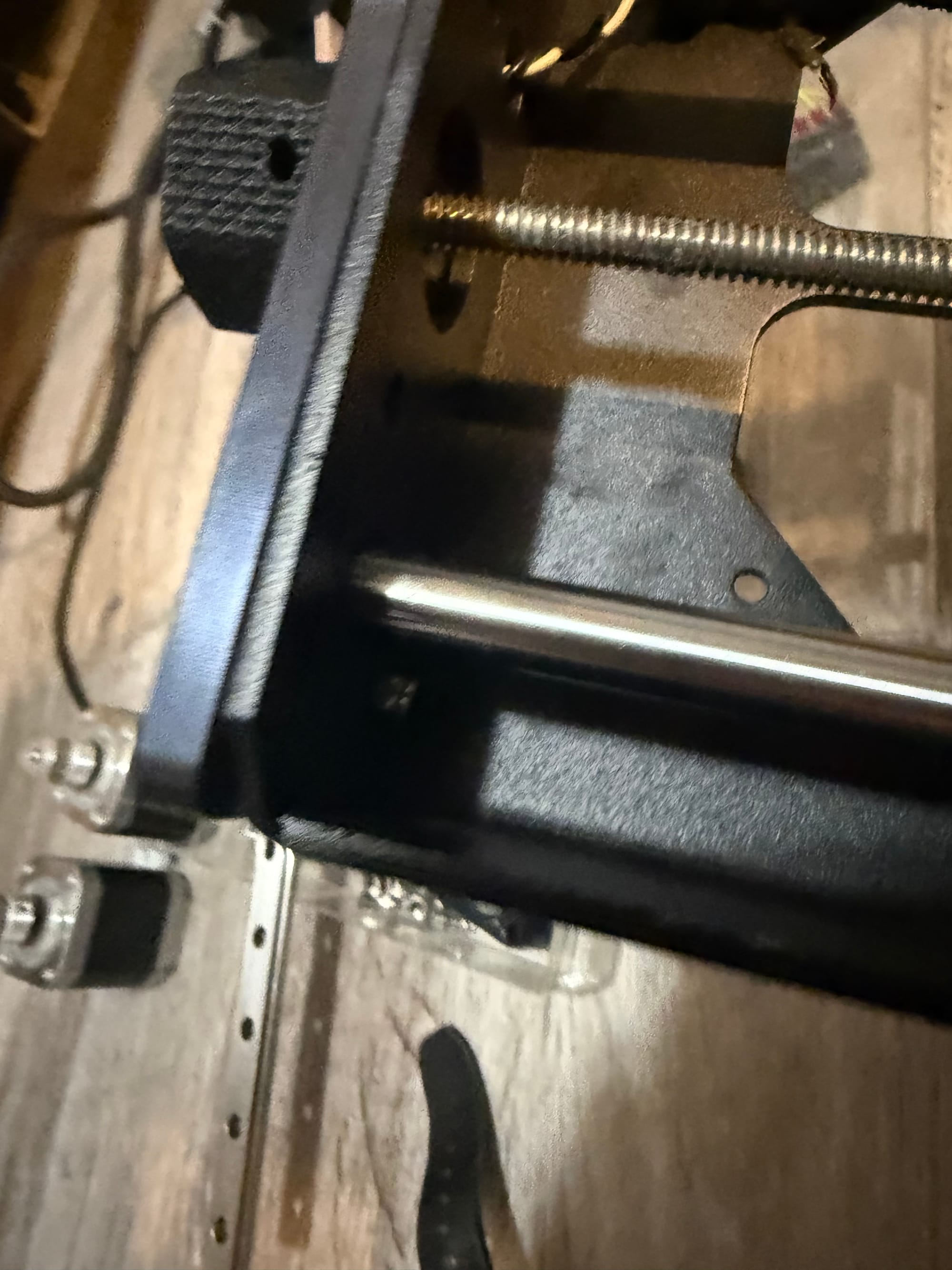
While attempting disassembly, I had a small issue trying to take out this nut since the hex-drive bolt just kept spinning in place and I couldn't hold it with anything I had at home, so I waited until I could go to work, borrowed a set of needle-nose pliers, and then held the nut so I could unscrew the bolt and get to the juicy internals of the printer.
Here is my haul (I threw away the metal frame of the printer, but kept the working power supply, display and rotary encoder, linear rails, gears for the rubber track, hotend, and some other parts)
Also, just from my existing collection, I already have:
- 608 bearings
- Arduino Uno
- Felt
- 40mm M4 screw
- 30mm M4 washer
- Spring
The parts I still need are:
- 2020 Aluminum extrusion (I can cut these to size if needed)
- GRBL CNC Shield
- Heat inserts
- PTFE pipe (I can find this somewhere)
- 10mm ID bearings (because my rods from the 3D printer are 10mm OD)
I will need to modify some of the components to fit my linear bearings, lead screw nut, and steel pole lengths, but these should be relatively easy fixes. Right now I'm going to purchase the heat inserts, GRBL CNC Shield, bearings, and 2020 Aluminum extrusion.
I got my heat inserts and 10mm ID bearings! The bearings fit on the poles, now I will download the STL files for the parts, turn them into editable SolidWorks files, modify them for mine, and print them.
Today I brought in my 2020 extrusions to work and cut them with a bandsaw to 10.5" to match the shortest of the lead screw or metal pole with linear bearing.
At home, I used a pair of calipers on the ID of the hole inside the 2020 extrusion, and it measured 5mm exactly. According to Google, to tap a hole to fit an M6 bolt, I need a 5mm drilled hole, which matches perfectly! (At least I thought...) To be safe (good choice!!!) I used the scrap extrusion I got from cutting the original size, and tried using an M6x1.0mm tap on the 5mm hole with my drill, clamping down the extrusion to my wooden desk with a Pittsburgh 6" C-clamp, I noticed a lot of resistance, and then eventually the clamp broke right through the bottom of my desk!!!

Naturally, I figured something was wrong with the tap or the hole, so I got an imperial drill bit slightly above 5mm, in this case my 7/32 bit (pictured below) that measured in at 5.4mm on my calipers. A usable thread pitch of 0.6mm as opposed to 1.0mm would be less strong, but would make the tapping job easier for my tap. Also, for my application, I don't think the M6 bolt is going to be under much strain.
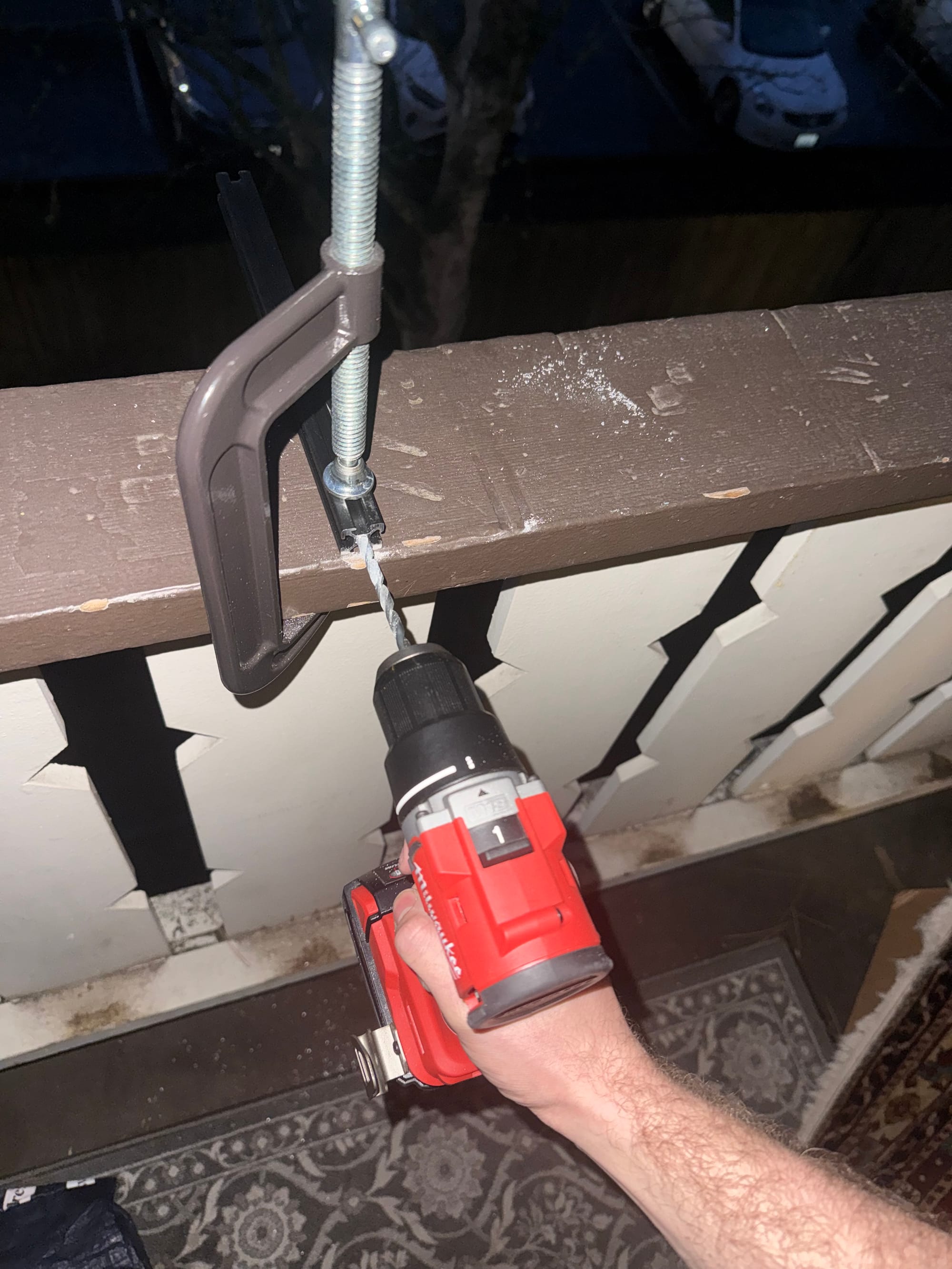
Before I could break another hole in my desk though, I went outside and used my solid wood balcony railing as a surface to clamp my extrusion to. First, I drilled the 5.4mm pilot holes into each side of both extrusions:
After this, I tapped the holes which went much better and more smoothly. No hiccups whatsoever. I then screwed in the M6 bolts to each side of the extrusions, obtained from where they were stored in my bolts/screws bin from disassembling something in the past.
Now I'm going to:
- Download stepper motor, leadscrew, extrusion, poles, and bearings into SolidWorks from some free CAD database library.
- Download or just observe JGJMatt's .stl files and 3D model to make my own versions based on the mounting gear that I have.
...5 hours later...
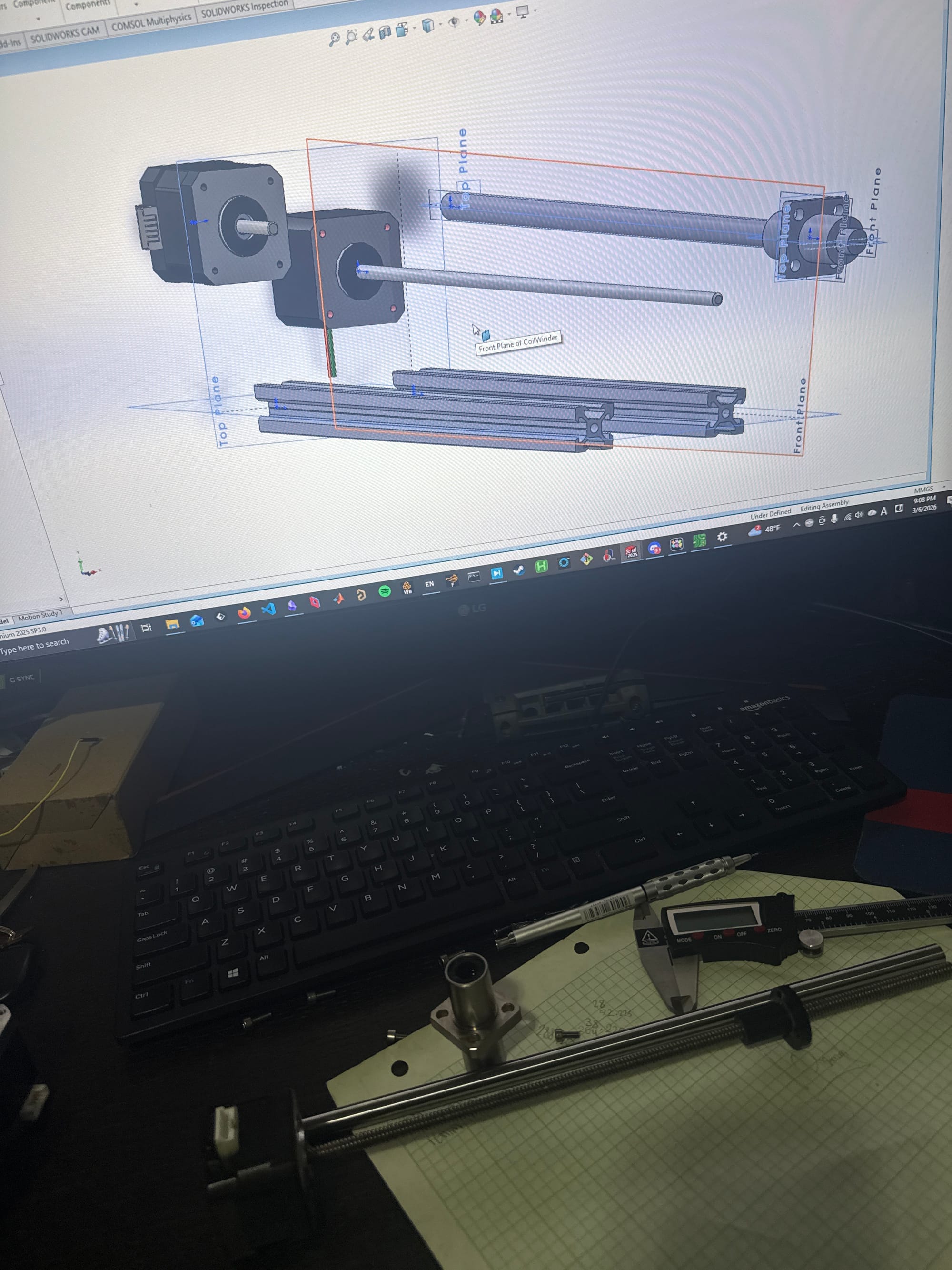
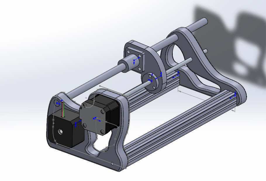
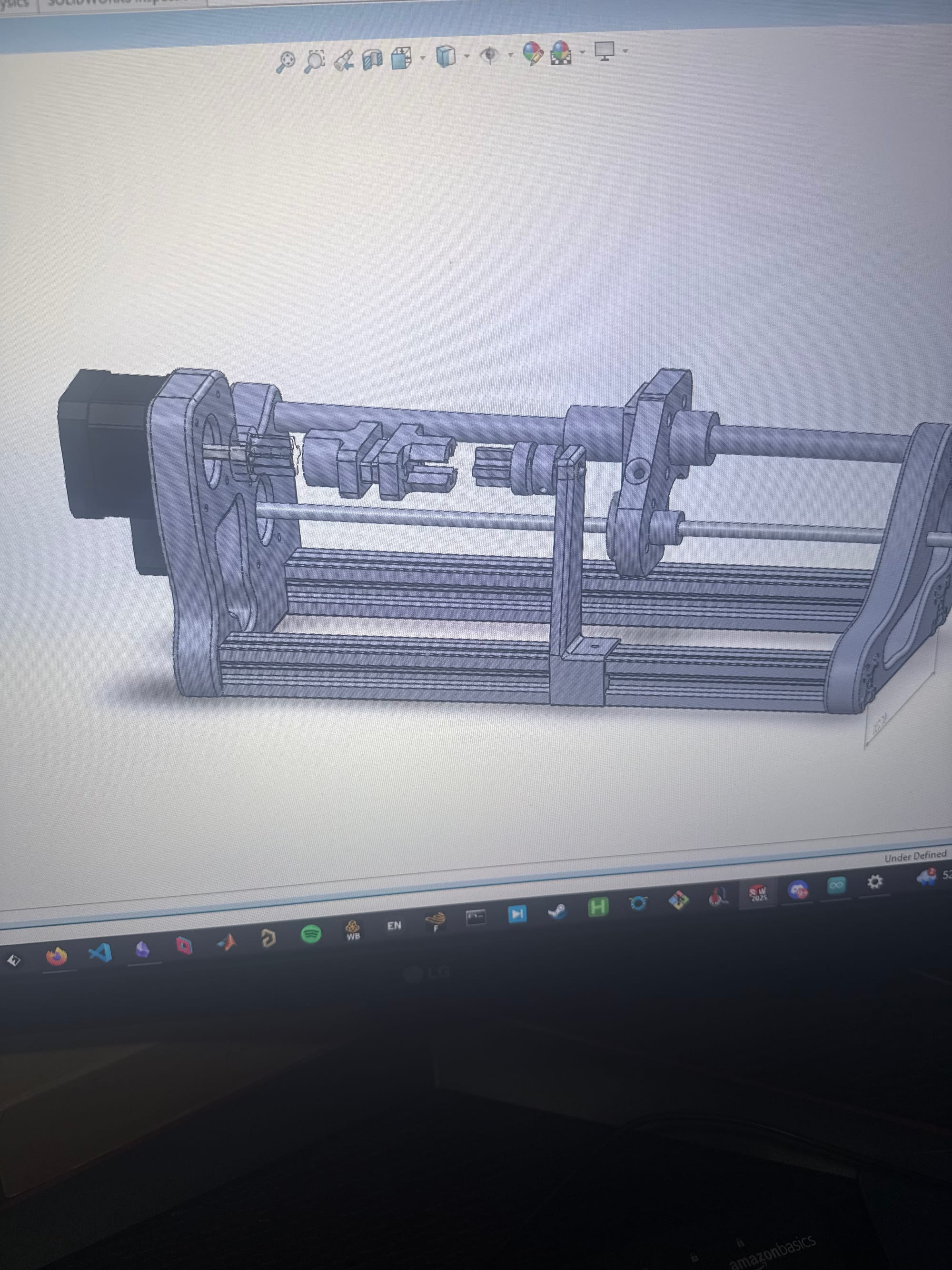
Phew! I'm not the most familiarized with SolidWorks so I had to learn quite a few new things and deal with some issues, but progress is definitely afoot! Here's what I've done, and the problems I still have:
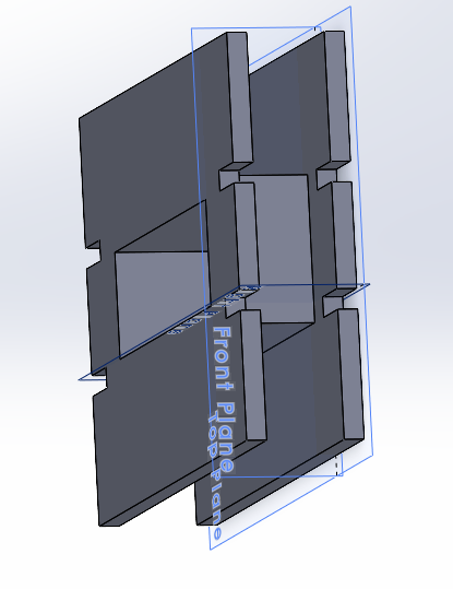
I redesigned the enclosure and components of the coil winding machine from scratch, since none of the original specifications fit my needs. This is because:
- My rod is 10mm diameter instead of 6mm
- My stepper has a leadscrew already attached and doesn't need a coupler
- My linear bearing is much larger and mounts differently
- My leadscrew shaft mount is different, and the leadscrew itself is shorter
This wasn't very difficult for the main enclosure, but the more difficult part is upcoming with the tensioner and bobbin mount:
- The tensioner essentially just needs to implement some resistance to the wire from bobbin to tensioner. In the Instructable, this is done variably via a screw, a spring, and a washer covered in felt. The tighter the screw is, the more force the spring and thus washer imparts on the wire as it attempts to leave the tensioner, and since the wire is held on the bobbin-end by some piece of tape or previous turns of wire, the wire is tensioned on the coil accordingly. This shouldn't be too hard to make, I just need to ensure that the enamel of the wire couldn't be scraped off in any location, and that the wire feeds smoothly through.
- The bobbin mount is interesting, as it varies between what objects I would attempt to wind. I could use the same mount to the stepper motor shaft as the Instructable, but my bobbins will be much smaller, so I think some other kind of universal mounting mechanism would be better, so I could just 3D print a mount for any ferrite cores I may want to mount, or their respective bobbins, easily, securely, and with a small profile.
- I have no clue why, perhaps because I referenced some faces of other parts when sketching the endplates, but my extrusions are phasing inside of one of the endplates no matter what I do. This shouldn't affect much except aesthetics, but it's still pretty annoying.
I'm going to 3D print the endplates while I sleep, and dream about a successful automatic coil winder..
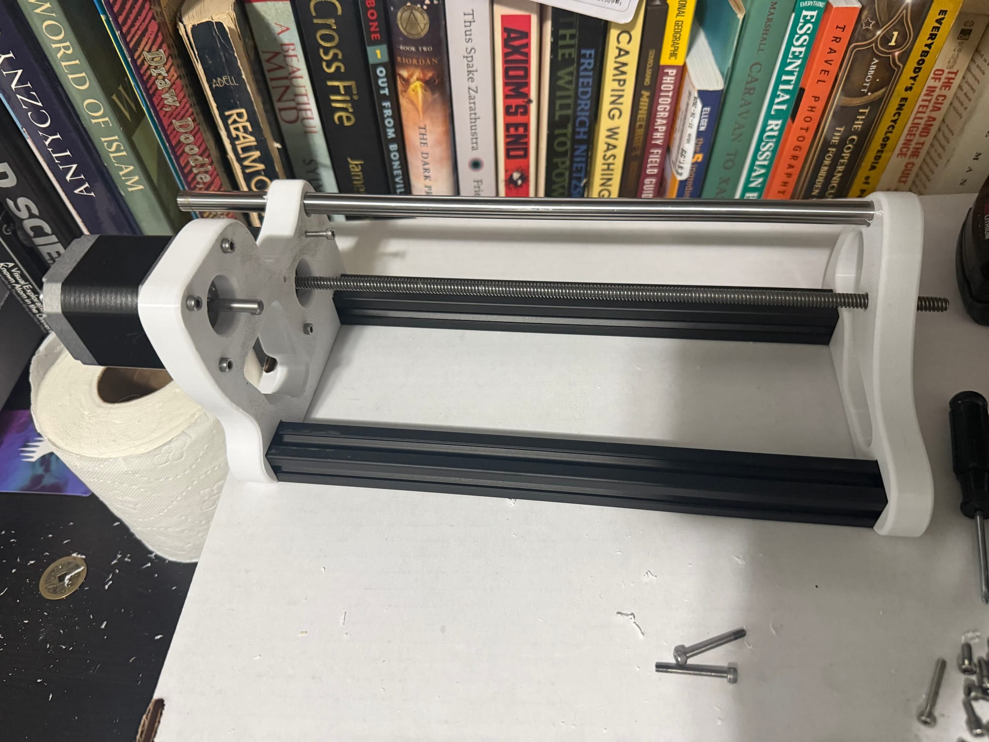
In the morning, I drilled the holes to be bigger since they are shrunk compared to how big they should have been based on the 3D model, and then I inserted and bolted the extrusions, steppers, and rod together:
I'm going to complete the tensioner and bobbin holder once I have access to my Windows computer at home again, which should be 3/8/26, since I'm out at UW today on 3/7/26 all day. I also have a lot of college apps due by 3/15/26 that I really need to get started on, so I'm attempting to crank some out this weekend.
3/8/26
Although I was supposed to do some college apps today (and I'm still planning to), I got really excited about finishing this machine so I:
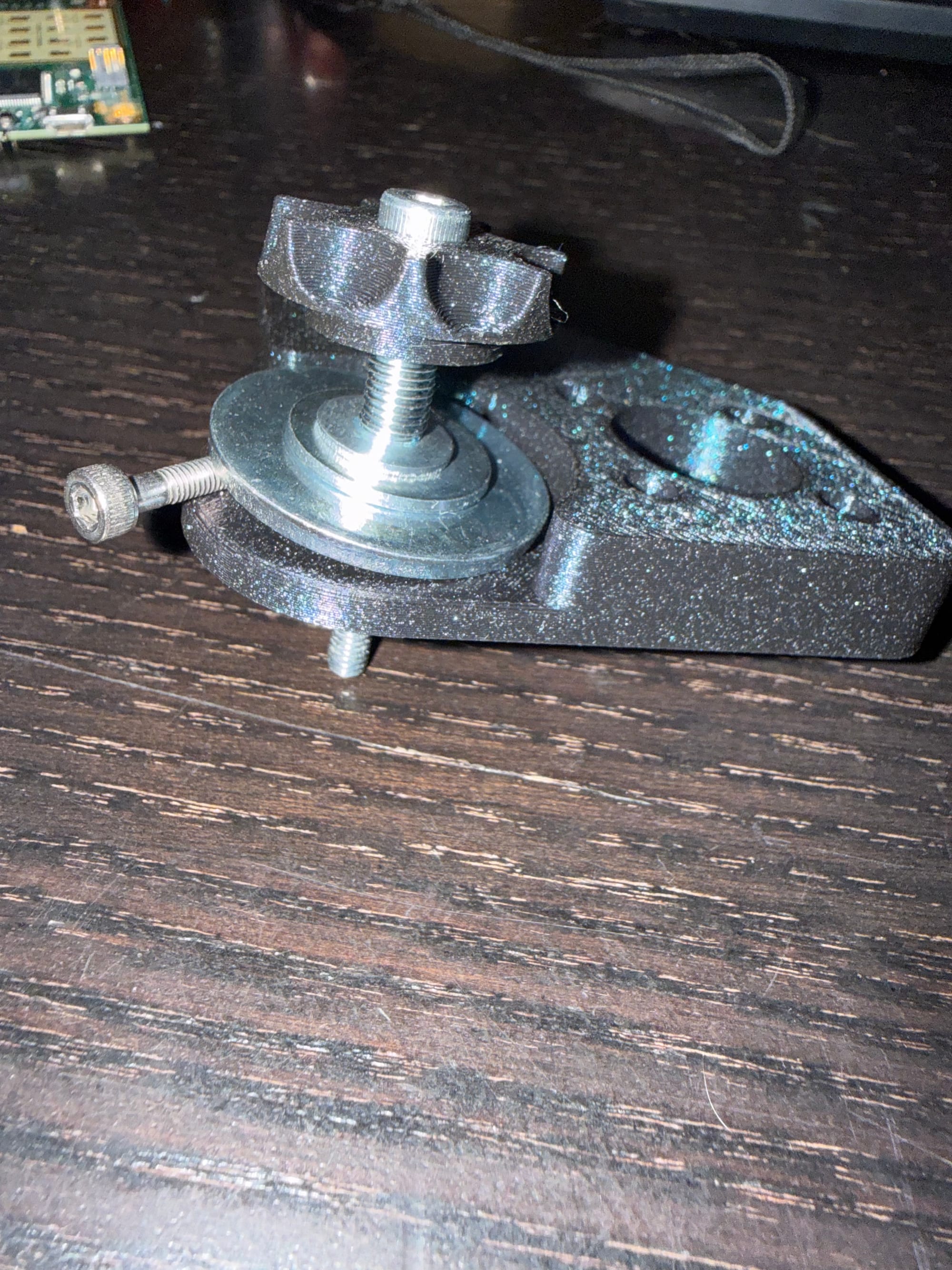
- 3D modeled the tensioner in the assembly (with some issues in converting entities to sketch references and fully constraining the movement of the model, but now it works)
- 3D printed it and the knob (stolen from the Instructable 3D models) in a new filament color, since I had to reload spools
- Drilled holes to be the right sizes for my bolts
- Put together a hierarchical set of washers in order to make the tensioner washer be 30mm, since the big washer had too large of an Inner Diameter (ID) and picked the tensioner spring out of an old pen
- Drilled a larger hole for the leadscrew, preparing it for smooth motion using a bearing I buy eventually or make myself (since I got the wrong bearings, I was meant to get them for the 6mm lead screw diameter, but I got them for the rod diameter 10mm, whoops)
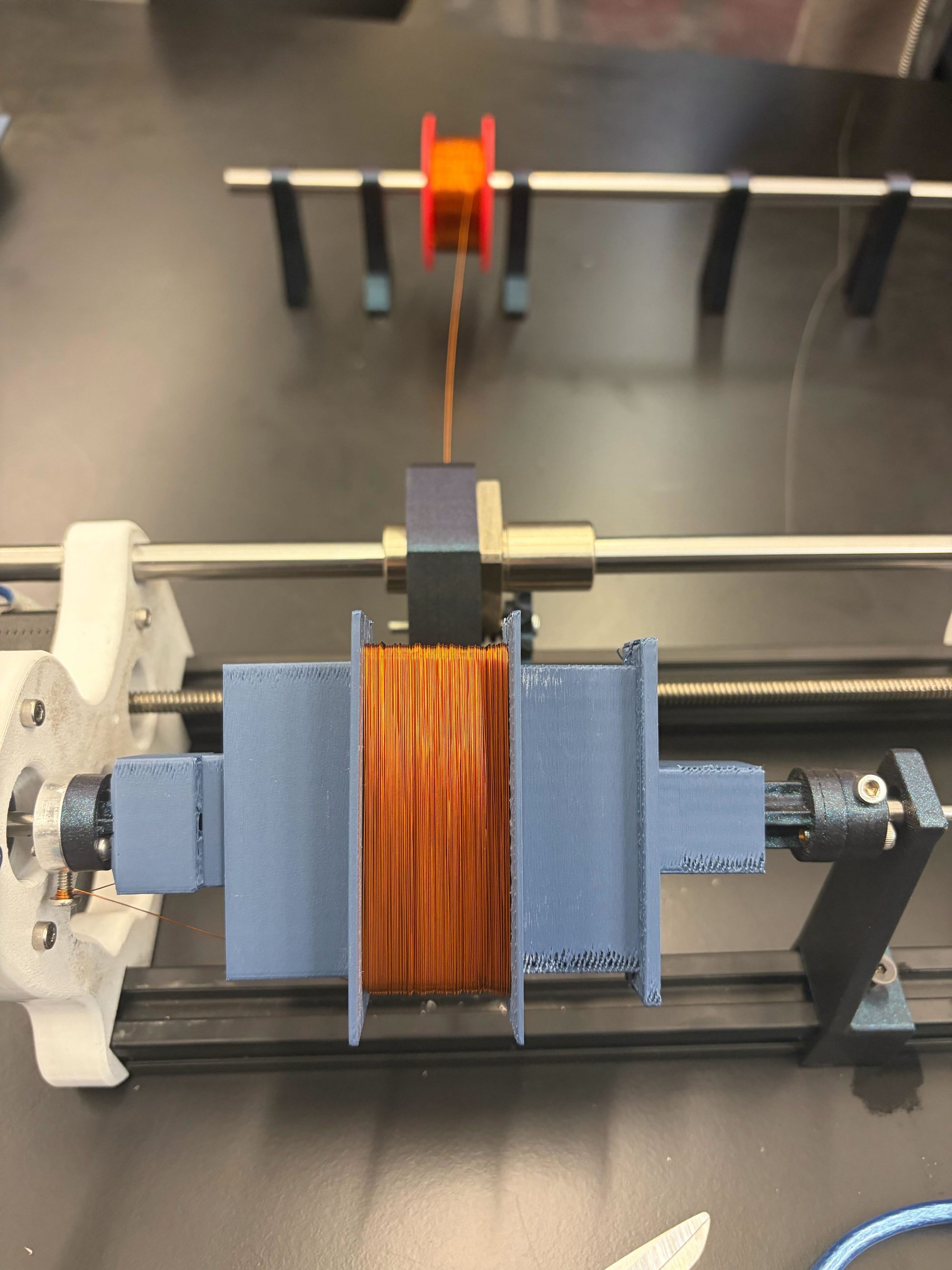
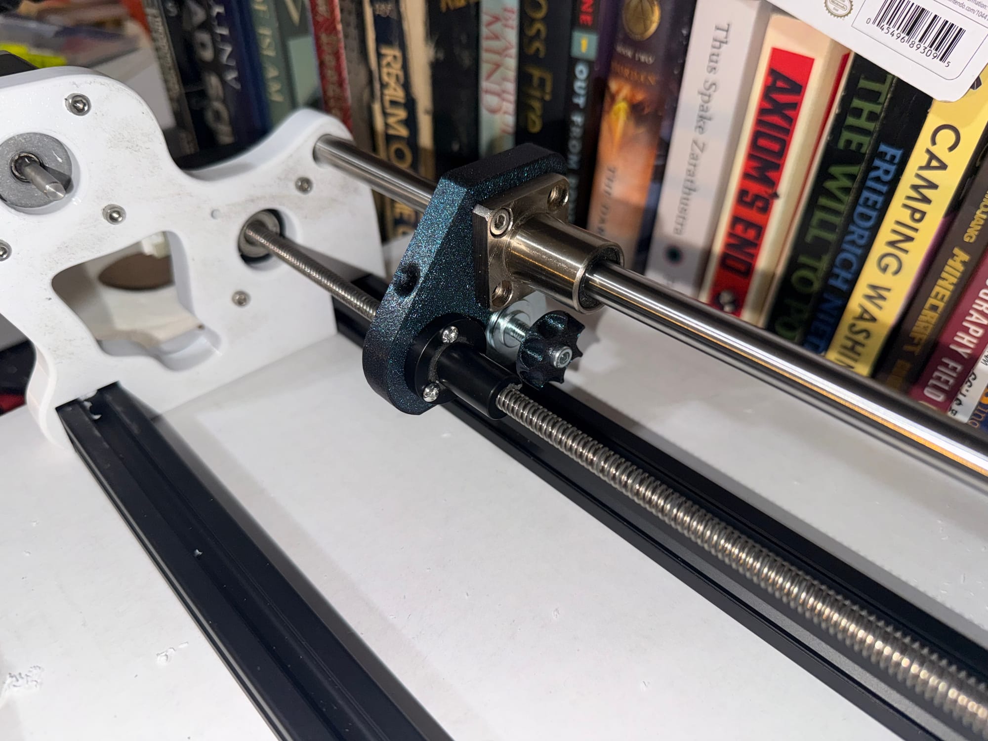
Assembled the new setup! Now all I have to do left is create the bobbin mount and put together the electronics!
Now I will do the following:
- Create a spindle that allows bobbin mounting on the 5mm stepper motor shaft through a mounting collar.
- Create a mounting stand that allows sliding on the 2020 extrusion (I have to be careful of tolerance especially with the non-circular 2020 extrusion profile, so I'll print some test prints to see how much I have to account for shrinking in the final product vs. my design for internal walls and holes)
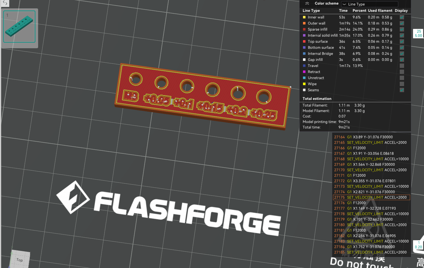
I'm going to use this X-Y hole compensation value tester using an M3 bolt, and from this, I found that +0.15 was the perfect compensation value.
3/11/26
Today I feel a little sick, so my goals aren't too ambitious. I got my CNC shield today though, it finally arrived from Amazon!! So as soon as I:
- 3D model new bobbin holder stand and spindle to rod and bearing (I have a matching rod and bearing combo, but the rod is only like 5mm in diameter and the bearing is 7mm OD 5mm ID, so my 3D model will have to follow that)
- 3D model a custom E-core bobbin with spindle mounting capability
- Print bobbin holder stand, bobbin, and spindles
- Wire up stepper motors to the CNC shield and an Arduino Uno
I can actually get to winding! It sucks that nothing is bottlenecking me now except for illness, but it is what it is. I'll finish this soon. I might not go to work tomorrow, so then I can likely work on it while sick.
3/16/26
I have been working on college apps for the past few days after being sick, and 3D modeled and printed some new parts. Unfortunately, I realized a few new things:
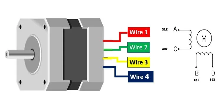
- The steppers from the 3D printer I got are 6-wire unipolar, and the stepper driver shield board I got has only a 4-pin output. I need to figure out how to drive 6-wire steppers from the CNC shield.
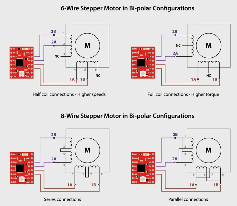
I am going to use the top left configuration for the leadscrew stepper and the top right configuration for the bobbin stepper. To find out which wire corresponds to the center taps, I'll use an inductance and continuity measurement. If there are continuity between three wires, and a larger inductance between one pair of those wires, the other wire is the center tap. I will use my DE-5000 LCR meter to test my steppers and provide my results.
JK! It turns out that because my mom threw away my bag of salvaged wires and cables from the 3D printer, the cables that connected with 6 pins to the steppers were thrown away and I don't have any connectors that fit. :( My possible solution to this is go to my local electronics store, Vetco Electronics, in order to find the connector somewhere ASAP. By measuring the pin width on the stepper connector, I determined it's a 6-pin 2.00mm pitch JST connector, which I can get from Vetco luckily:
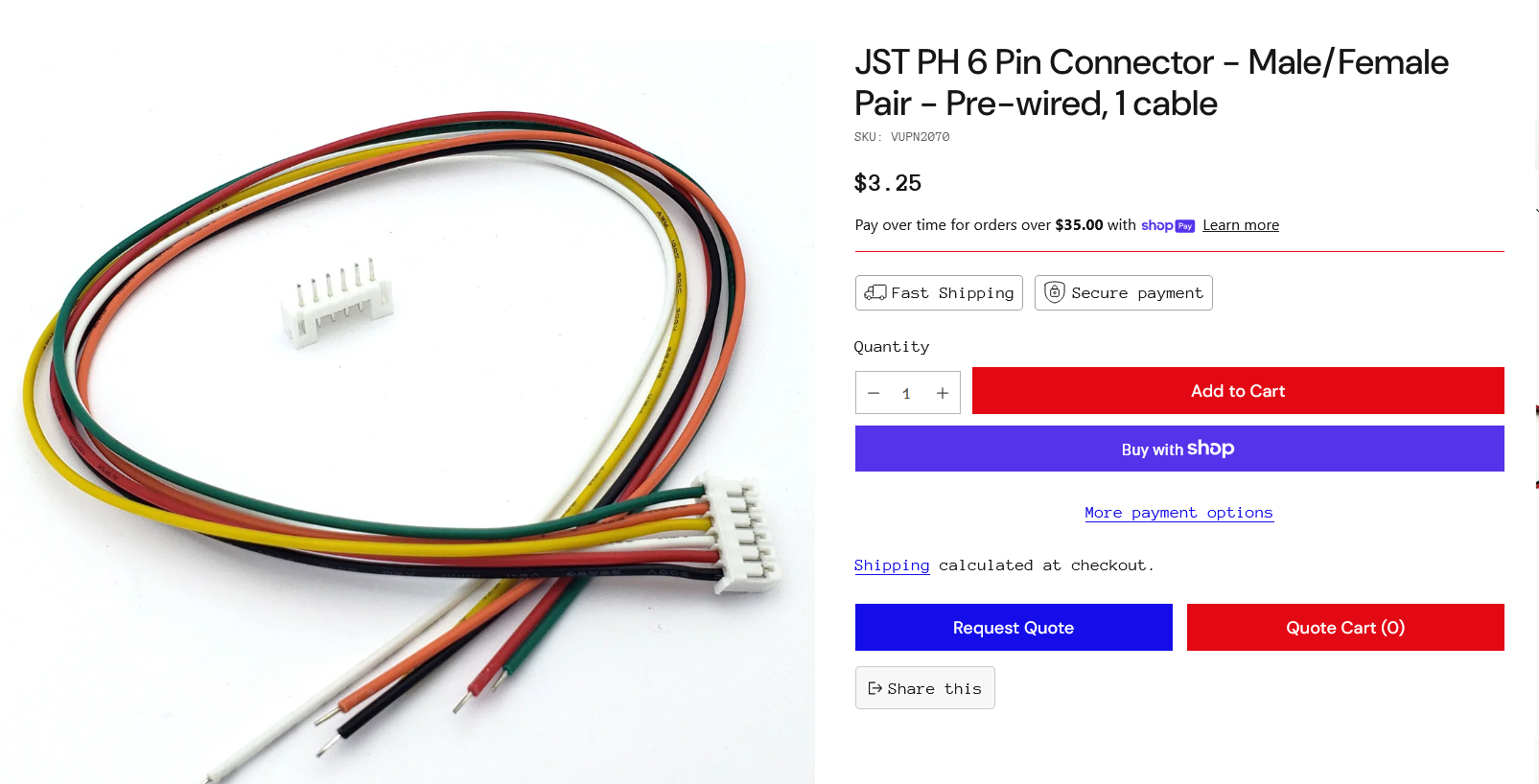
And then only use 4 of the wires for the stepper driver. I'll bring the stepper motor to the store tomorrow and get these connectors.
3/17/26
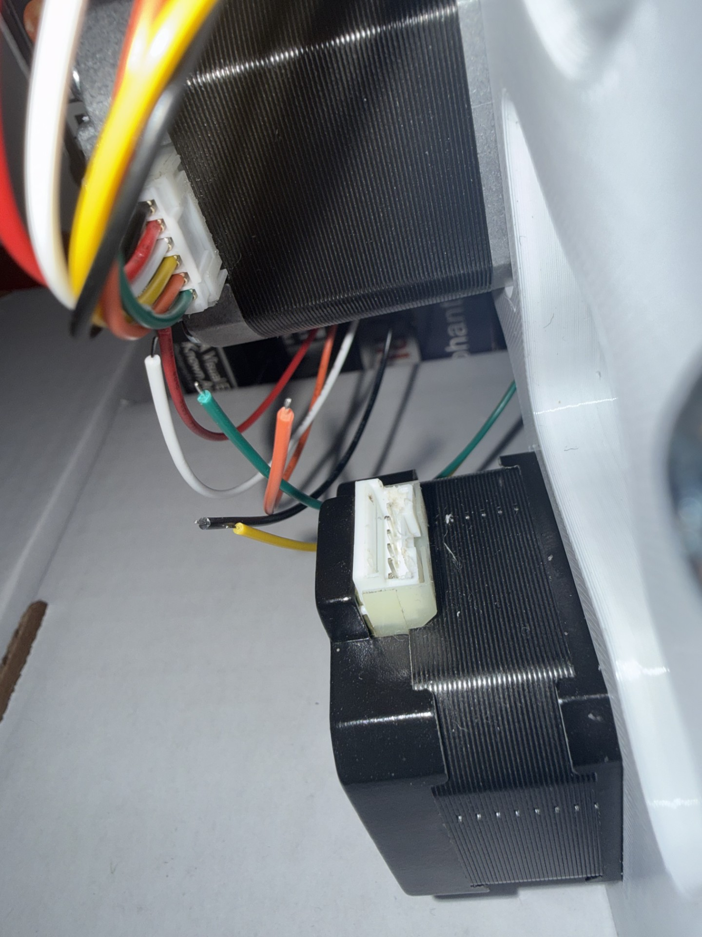
...In what might be one of the most infuriating moments in my life, as I spent a precious 2 hours after work driving to and from Vetco to get these connectors and a grab bag of random shit to try and make my time somewhat worth it, when I got home, I realized that my connectors don't fit in the leadscrew stepper motor female connector. One of the connectors fits, the one with the example stepper that I bought, but the other one just doesn't fit at all.
I melted both of the connectors to try and force them to fit together, but no fucking luck.
And guess what? I can't even take the stepper apart, because the phillips head bolts on the backplate of the stepper are cammed out. I just LOVE Phillips....At this point, I have no clue what to do. It's already melted, so I don't even think the correct connector would fit. I am thinking maybe I could try:
- Solder small wires and epoxy to ensure some insulation??
- Maybe just cut the 2 pins to the 2 coil ends that I won't be using to give me space to connect the 4 wires I do need?
- Or maybe just give up and buy a leadscrew or stepper that has 4 wires? That would be annoying and I hate giving up, so I don't like that option.
3/18/26
Alright, at work I used a feeler gauge to pry the tabs on the connector up, and remove the Molex socket crimp connectors. After doing this, at home I checked the resistance of the connector pins with a multimeter and, interestingly, only 4 seem to be internally connected, with 2 being disconnected (extremely high resistance) from all other pins. This is good news, as my option 2 seems the most plausible. For my leadscrew stepper, the pinout and connections seem to be as displayed below:
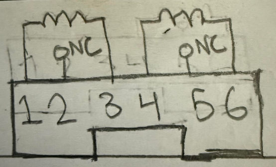
So now I am connecting the 4 Molex sockets to the pins of the connector, and then hot-gluing the inside of the connector to keep it insulated.
After using my soldering iron a little to melt the connector and allow solid connections to each of the pins, even adding a little solder to one of them (no flux, I probably should have used flux though), I used the trick of shorting each coil individually and testing the motor's physical resistance to turning to see if they are in fact connected (More resistance means one of the coils is shorted), and both coils work via this test! I don't feel too confident about the other connections since the Molex socket was spreading apart after sliding onto the pin, but we'll see if it works during normal winding operation. The faster it can go, the faster I can wind.
Now, to connect my wires with stranded ends to the male jumper pins on the CNC Arduino shield, I am using the pinout below:
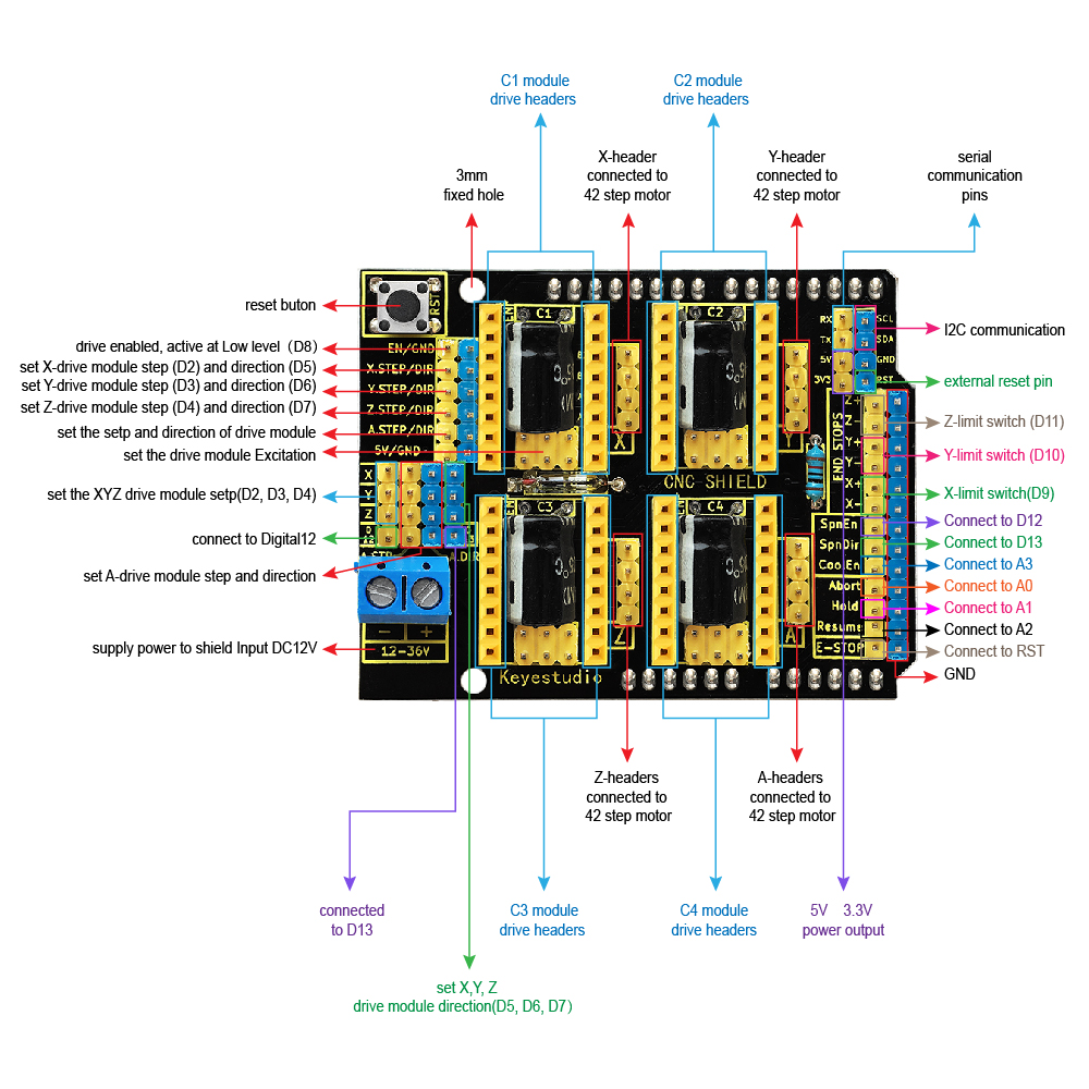
And the common assumed pinout of a 4-wire stepper:
I now crimp female Molex connectors onto the wires and use 4-pin header connectors to turn the wires into 4-socket Molex headers that I plug into the CNC driver shield.
Then I used 14AWG stranded wire, 2 male banana plugs, 2 banana plug covers, and 2 16AWG ferrules (since 14AWG was too big to fit in the screw terminals, I cut some strands off to make the end of the wire fit 16AWG and those fit in the screw terminals perfectly) to connect 12V from a benchtop power supply to my CNC shield.
Now I am downloading GRBL onto my Arduino Uno with the CNC Shield. To do this, I am downloading the GRBL source code, uploading the grbl folder as a library onto the Arduino IDE, and compiling the example sketch for "upload".
Now that the GRBL sketch is uploaded, I can create GCode using the following Excel spreadsheet, and then send it to the Arduino via UGS. First though, I tested out the function of the coil winding machine through UGS "jogging" commands which just send short commands via me clicking my mouse.
Uh oh...the leadscrew stepper is grinding and not moving at all....that's not good...it might be something internal, or it could be a short across some of the pins.
I had a feeling the connections weren't good on the pins, and I think I may have been right. As a solution to this, I'm going to just ignore the connector, and solder directly to the PCB inside the stepper motor housing. Thus I'm just going to try and take off the backpanel of the stepper motor first...wait, this is the one with the cammed out bolts! Screw it, I just drilled out the cammed bolts and replaced them with new ones.
Now that I open the backpanel, I see that the traces of the PCB are under some epoxy, and there are some flakes of metal from my drilling that fell into the stepper motor magnet chamber and are causing some rotation issues. I had to painstakingly clean these up, and only then when I put the backpanel back on did the stepper motor turn as expected. It actually turned much smoother than when I started, so there must have been some flakes in there to begin with.
In regards to the connection, I again said fuck it and ripped the connector off, and luckily the pins inside the plastic housing didn't break off, so I was able to just use 4 18AWG stranded wires, do the same Molex 4-socket header connectorizing on one end, and then directly soldered and hot-glued the other end. I think this is a better, more permanent solution.
Now when I connected everything together and turned the power supply on, I got the following results:
The winding stepper being tested
Both the winding and leadscrew stepper being tested
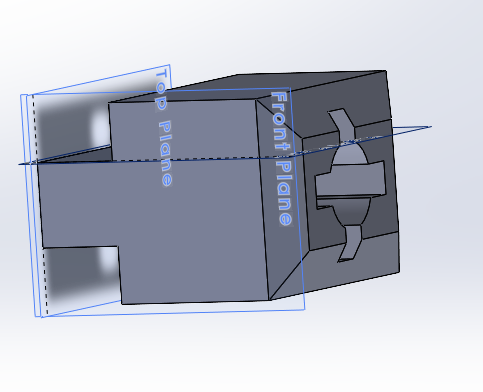
You may have noticed that the bobbin mounting mechanism is very much improved. This is because in the meantime of dealing with stepper issues, I had 3D modeled the coil winding machine assembly with an example bobbin mount that I used based on an E-core ferrite core I had laying around.
Mounting the bobbin to the stepper and the bobbin holder stand was a little more difficult than I thought, thus I had to model and print a lot more components than I was expecting. Getting the right dimensions and bolt holes was taking a while. Overall though this part went somewhat smoothly.
- I used heat-set inserts for the center of the bobbin halves so I could use a bolt to fasten them together
- I used a custom (3D-printed) and owned (metal) shaft collar for each end of the bobbin mount, with a plus-shaped spindle coupler attached to each end that allows quick-swapping of bobbins similarly to the original design.
- One problem, however, is that there is quite a bit of backlash with these couplers. In my next iteration, if this proves a problem, I can simply tighten the clearances I added (about 0.2mm for each hole) to make them a snug fit.
- Another problem is that the vibration of the stopping and starting of the steppers (as opposed to continuous motion) undoes the metal shaft collar and eventually results in no rotation of the bobbin. To solve this, I simply am 3D-printing another custom shaft collar and will be drilling the hole larger to accomodate the 5mm shaft instead of 3mm.
3/22/26
I just tested with UGS again today when I put the wire in the tensioner, and there is a dreadful grinding noise that lowkey scares me when I test out the bobbin stepper. I'm saving that problem for another day.
3/26/26
Through a few days of thinking, playing around with the G-code generator script, and pursuing some other projects and tasks, I found an issue with winding the EE cores. Because they have a rectangular center-leg, the G-code google sheet formulas won't work for them and I'll have to slightly modify them for a rectangular perimeter. I want to still use the EE cores I have because they are the best for HV transformers due to their closed flux path, low leakage, and proper winding window (as illustrated in Yiou He's thesis).
I will follow a design similar to this:
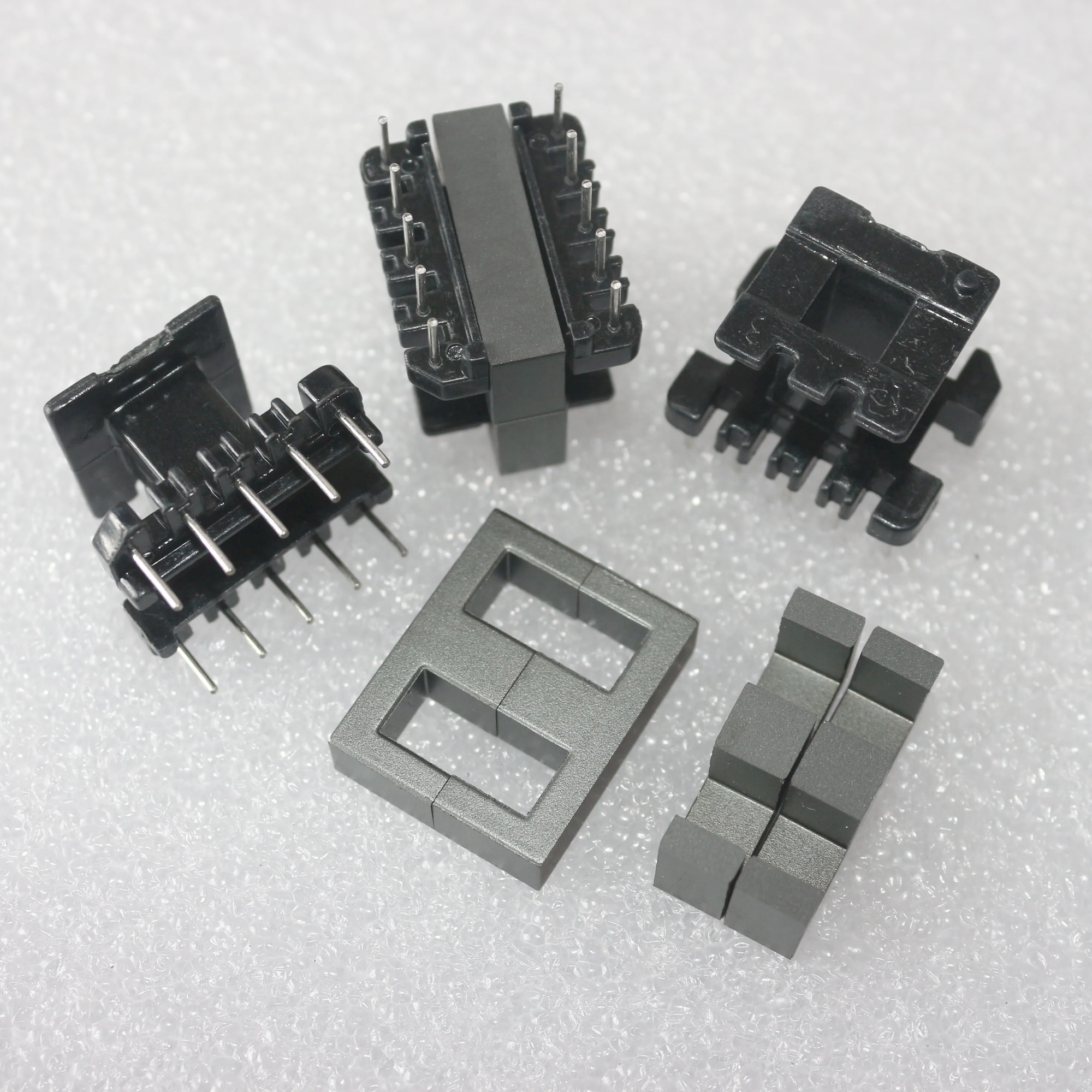
Or this:
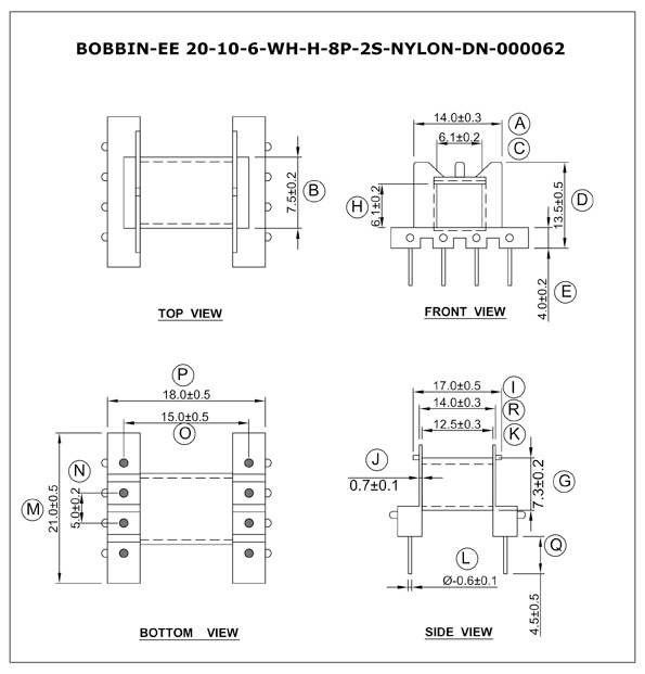
But with some kind of mount to the coil winding spindle on the ends where the center-leg is inserted.
During my previous HV transformer value calculations from the transformer and inductor optimization script derived from Yiou He's thesis, I've noticed that the window fill % is around 20% maximum, so the bobbin taking up some of that area shouldn't be much of an issue at all.
My tasks now are:
- Build a new bobbin
- Fix the spindle collar to be metal still
- Fix the G-code sheet to allow for my roughly rectangular perimeter
- Spindle coupler backlash/slop issue
For the G-code issue, I realize that I have to do a few things in UGS and it's not just a plug and play procedure.
- Manually move the tensioner to the left edge of my bobbin and click "Reset Zero" in UGS to home the leadscrew since I don't have a limit switch or way to denote the bounds. Maybe I should implement this, but manually moving the tensioner for the bounds of the bobbin shouldn't be too hard. The coil length parameter then takes the rest of the linear movement of the tensioner into account.
4/2/26
Today I learned about GCode and then worked on configuring the GCode generator for my use-case and it's actually a lot easier to handle than I thought. I learned GCode from this website, with the important stuff written here:
GCode is just a list of instructions sent to a machine line-by-line. The anatomy of every line is:
- Command
- Coordinates
- Speed
There are a lot of commands in GCode, but the most important are below:
G21 ; use millimeters
G90 ; absolute positioning
G01 X5.0 Y100.0 F10.0 ; move to X=5, Y=100 at speed 10
M02 ; end program
When changing the google sheet to take into account rectangular bobbins, I first downloaded it and began editing in Excel, then noticed that some of the formulas were missing from some cells, the formulas weren't dragged down through all of the columns, and the equations for bobbin "diameter" and the wire length took into account circumference-based equations (duh), so they needed to be changed to perimeter-based.
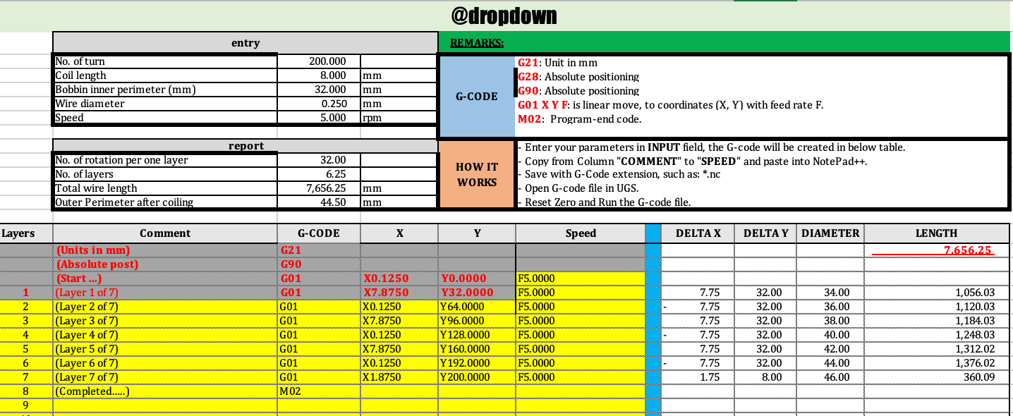
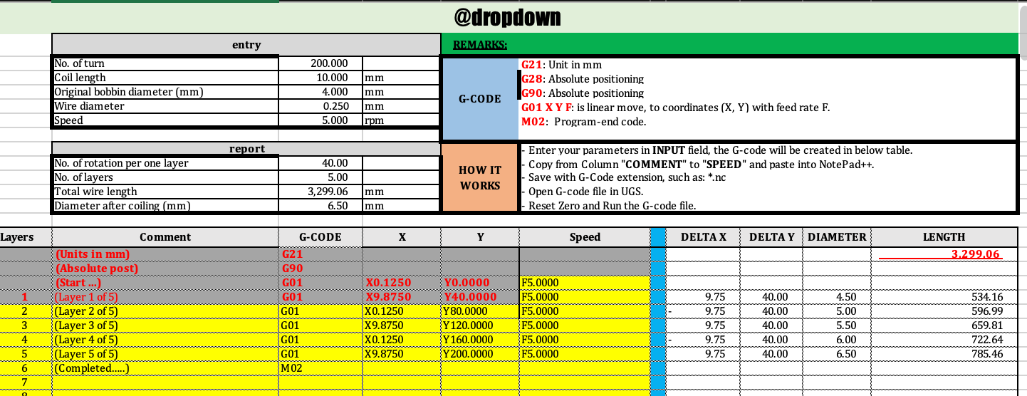
After fixing these issues and creating a "rectangular bobbin" sheet and a "round bobbin" sheet, then testing with some realistic input parameters, the outputs seemed to be real GCode and should work with UGS. If they don't, I know that UGS is the problem and will need to be configured differently. Thus my tasks now are:
- Upload real parameters to GCode generator
- Upload GCode to UGS
- Home the coil winder (after fixing mechanical issues and printing new spindle)
- Begin winding my first coil!
4/3/26
Right now I'm printing a new bobbin architecture, but testing the old one so I can make my coil winder work as intended.
I keep getting an error on my UGS page when exporting the sheet content as a .nc file. I realize that UGS probably doesn't know how to translate commands in mm to turns and linear movement with my leadscrew unless I find the translation myself or its implemented in the sheet, and since my implementation for the leadscrew is different from the Instructable, I'm going to figure out how to make the commands translate accurately.
In UGS there is a Setup Wizard I am using to calibrate the coil winder. My leadscrew stepper corresponds to approx 62.5steps/mm, while my bobbin stepper (naturally, since most steppers are this way) corresponds to 200steps/rev. Unfortunately though, there is a very loud grinding noise at some values of steps/mm or steps/rev. I think this is due to the stepper not using microstepping for the commands that exactly correspond to a multiple of their steps, but it causes a ton of vibration and is quite annoying since it appears exactly with the most accurate values. I want to purposely have microstepping occur to make the stepper move smoother.
I messed around with the calibration, and 3200steps/rev for the bobbin spun EXTREMELY fast, I didn't even know steppers could move that fast!! It also was much smoother, but that doesn't necessarily fix my issue. I want it to be accurate, speed irrelevant. I also need the GCode uploading to work, and I'm still having the error. I might just redownload UGS?
- Mess around with microstepping to make the bobbin spinning stepper move smoothly and quietly
- Fix UGS to allow me to upload my GCode
- Fix the backlash on the bobbin
- Add more tension to the tensioner, possibly using plastic instead of felt, since the coils are loose. Also could be because of backlash
My new bobbin holder just printed with new clearance dimensions. This time, I made the hole only 0.1mm larger on each side than the spindle, and made the two halves press-fit together with dowels, since there won't be any force pulling them apart during winding.
New low backlash bobbin mount held together by dowels!
4/6/26
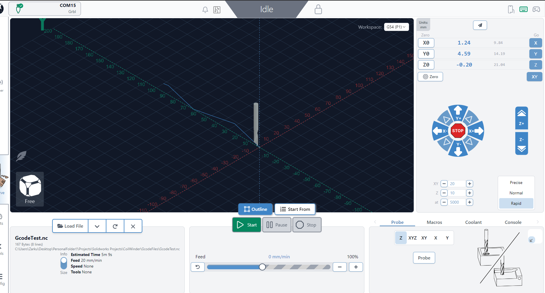
Today I downloaded a new Gcode sender app on my computer called gSender, and this one works somewhat, although because I didn't configure the software as intended, I don't think the steppers are calibrated correctly or referring to the correct ones. It does actually take my GCode file and produce movement on the output though.
4/9/26
After trying gSender out again, it seems like gSender is actually producing the intended output of 5rpm for the bobbin stepper and movement of the leadscrew stepper from wherever it starts, however the loudness of this machine is difficult to handle, and it vibrates on my desk, moving itself around. Unfortunately, after messing around with gSender's settings, microstepping isn't an inherent option, I think that's because it's hidden within feed rate? Regardless, after messing with some settings the issue never resolved. Here's a video of it working:
Original stepper motor noise issue (not an issue for the leadscrew stepper)
I thought perhaps the loudness could be not directly due to microstepping, but rather because the stepper wasn't receiving enough current and the wires were adding some resistance because they were thin (about 22AWG I would guess) so I used another stepper motor I had lying around that was actually a bipolar stepper with 4 wires instead of 6 (Probably should have used this to begin with, but oh well).
New stepper, same issue.
Now that it is shown that the stepper is not the issue and I know the operating voltage is not an issue (since I've been changing it randomly between 12 and 30V to test things out, 12V seems the quietest), I looked online and found this Reddit thread on a similar topic, and the people in the comments said to try a few things:
- Lower the current into the coils with the driver trimmer pots
- Mess around with the jumper pins under the driver board (seemed to fix OP's issue, but they forgot exactly how)
- Use microstepping (duh) or a different driver board (N/A)
First, I'm going to try lowering current with the trimmer pots. I am turning in increments of 90 degrees...
It turned out (no pun intended) that turning the trimmer pots clockwise makes the current (and thus loudness and torque) decrease, and turning them counterclockwise does the opposite. Varying voltage has a similar effect.
I also changed the feed rate which increased the loudness during operation, and the speed in rpm which didn't do much for loudness and may have even made it more quiet. I'll increase the speed beyond 25rpm and see what happens...
Nothing really happened, same loudness but increased speed. Overall it seems like current is the knob for loudness, but has the tradeoff of lowering torque. If my steppers lock up ever due to the tension in the tensioner, then I know to increase the current. Since the tensioner is felt fabric though, I don't think this will be much of an issue. I'll keep the current low for the main bobbin stepper, in the middle for the quiet leadscrew stepper, and keep the voltage around 15V. I'll also make the RPM high so my winding can be done as quick as possible.
- I next calibrated the leadscrew stepper in gSender, noticing that it's difficult to get a precise value for the initial position of the tensioner to dispense the wire. Perhaps I should implement some kind of mounted device that allows easy caliper measurement of the difference between the beginning of the bobbin window and the hole opening of the tensioner.
- I also noticed that the bobbin spindle wobbles ever-so-slightly, and that the bobbin is tilted by a small amount in the spindle. If I'm not supervising the coil winding this could be an issue, but in this HV transformer context, I think I'm going to be supervising the coil winding.
Now, after testing a few times with real wire and a real bobbin and setting up the winding by doing a few initial turns, the bobbin stepper reverses direction after a few turns. This happens also without any wire, which is weird. This also happens with a lot of different current values, especially when I just let it run for a few seconds. I'm guessing this has to be something to do with the PWM values going out of phase and reversing polarity or something.
I'll continue this another day, but I'm getting a little less hopeful about this coil winder being precise and working well. Maybe winding the HV transformers by hand is just something I'll have to do?
Also, since I haven't done this until now, I'll explain exactly the workflow I expect for these HV transformers with the coil winder.
Winding Workflow
When making a HV transformer, I will initially apply teflon or Kapton core insulation to the core before winding anything or use a permanent bobbin, then:
- Wind the primary slowly, letting the windings fall side-by-side. For each layer, stop the winding and apply a few layers of Kapton.
- After done winding primary, apply more Kapton layers.
- Wind secondary, also being sure that I apply layers of Kapton between winding layers.
- Once done, use calipers to find an adequate shim air-gap to apply to the center leg.
- Create a mold for epoxy casting, and use a vacuum chamber to cure the transformer epoxy without air bubbles.
Repeat for however many parallel input, series output transformers I need. Note that for HV transformers, I'll likely create multiple GCode files for a transformer, one for each layer, so that the coil winder stops between layers allowing us to place interlayer tape and superglue.
Todo:
- Make the exit hole for the wire smaller, likely using the PTFE tube idea that the Instructable creator had.
- Fix the stepper reversal issue. Initially this wasn't an issue, but I fucked with something that randomly caused it. Perhaps the speed? Current? (Not tension bc. it reversed without wire)
4/13/26
My motor configuration in Gsender seems to work when manually stepping the steppers accurately. The calibration gave me:
- Bobbin Stepper travel resolution 200step/mm, maximum rate 100mm/min, acceleration 5mm/sec^2. Direction is negative compared to the default.
- Leadscrew Stepper travel resolution 63.02step/mm, maximum rate 500mm/min, acceleration 12mm/sec^2.
I think an issue is that the tensioner isn't providing enough tension. I either need to get a stronger spring (I'm using a pen spring) or a harder clamping material (right now am using felt), or both.
NO WAY!!! I tested with this new calibation at 100rpm GCode after homing the steppers to 0 positions, and the whole thing ran seemingly without major flaw!! I think me not zeroing out the stepper coordinates was one of the issues!! One new problem though, is that the leadscrew stepper seemed to move a little more than 8mm even when calibrated, so I'm going to check calibration again. This is good news though! Hopefully if nothing else messes up, the coil winder should work as expected! I'll make the coil width 6mm now to give a little margin in the window width of the bobbin.
It works!!! To be fair, this is without the wire actually being wound around the bobbin, but I'll take the win for now, and wait until later to potentially be disappointed with its performance lmao.
4/18/26
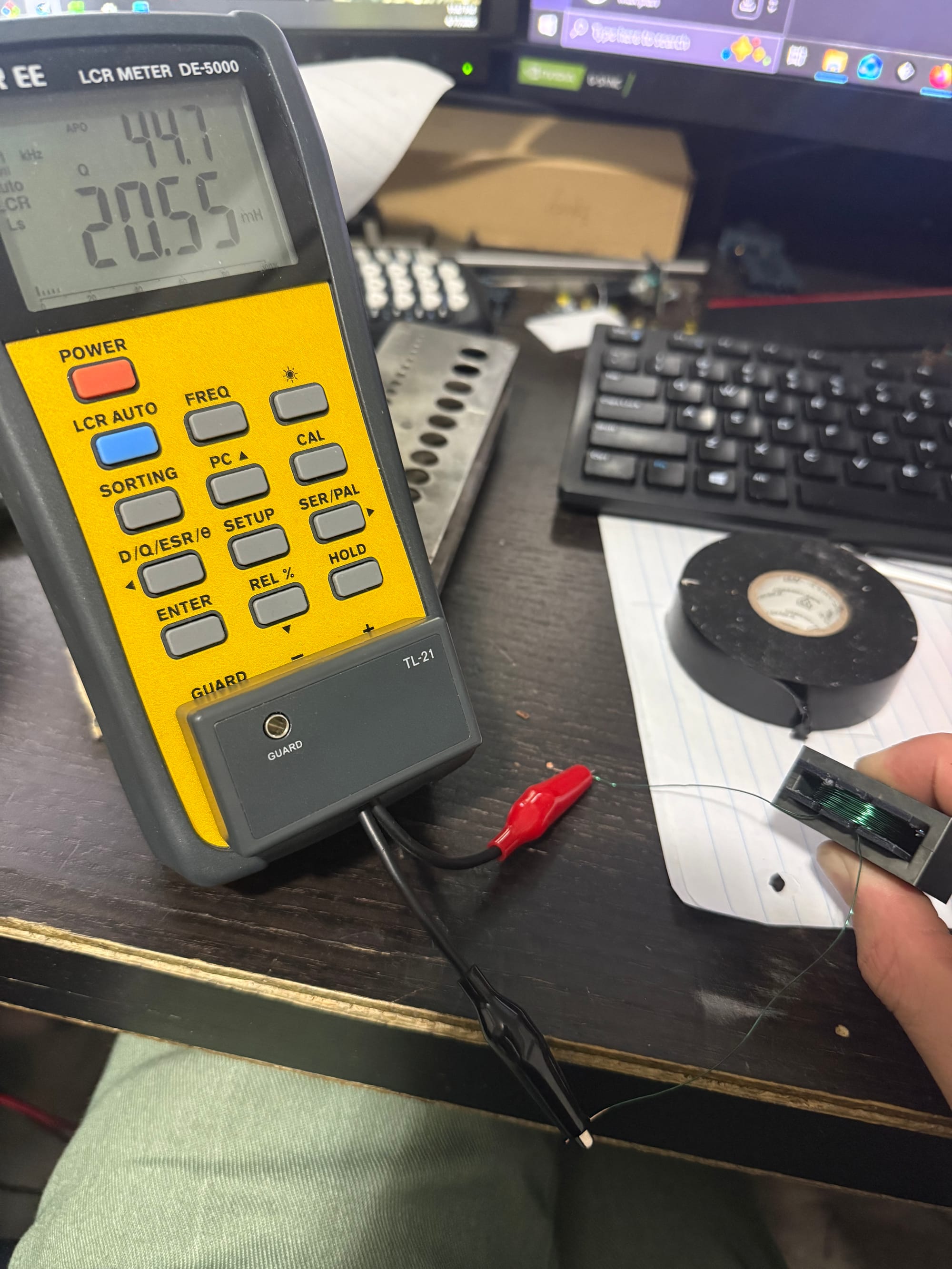
Today I wound an inductor with 100 turns from the coil winding machine and it worked great!!!
4/21/26
Today I had some free time so I decided to find some way to increase the tension on the tensioner. I found a strong metal spring I could use and it fit perfectly in the existing knob slot. To compensate for the tension force the spring would impart, since before I had just self-tapped the PLA with my machine screw, I heat-inserted an M4 insert which should increase the tension I can apply without the bolt slipping.
I also covered the washer that touches the wire with electrical tape to avoid any possibilities of scratches. I covered it with a few layers to avoid any possible scratching, but I am still slightly worried about the brass insert and the screw which the wire could still touch and be scratched by. I think if the wire just goes through above the hole where the bolt comes through, it shouldn't be an issue, and thus elevating the wire on a stand might be a good idea.
OMG I just got an idea looking at my room floor!! A ferrule is perfect for the wire directioning since it's just like a needle but with a wider diameter!!! I can just use some kind of two-part clamping assembly to hold the ferrule in place, or perhaps superglue, or heat, and then the wire should thread through it really easily onto the bobbin!!
Something I noted while winding the transformer are the most important things to consider during the process:
- The coil feeding mechanism is flawed and the wire can easily get tangled, so some kind of stable holder is REQUIRED for winding.
- Tightening the non-stepper side of the bobbin is also REQUIRED since the vibrations cause wobbling and movement that messes up the coils
4/22/26
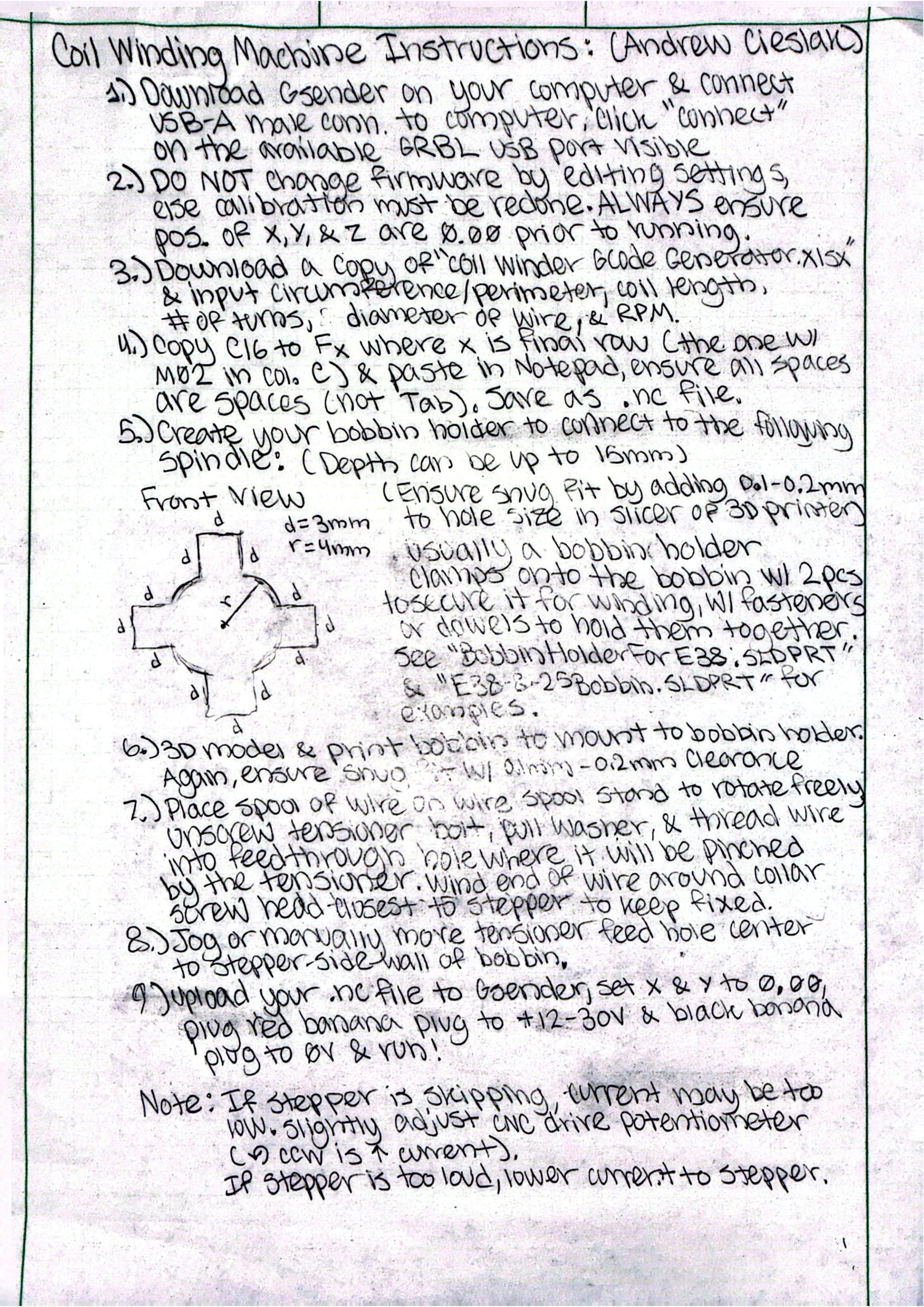
At UW I made this coil winding procedure page for the capstone students to use:
But when I plugged in the device into their power supply to work on it, the driver board blew up. I bought a new driver board.
The heat-insert also got pulled out when I screwed in the tensioner bolt quite a bit more to add tension, so I re-modeled and printed a better tensioner design that is thicker to allow full contact of the heat-insert to the PLA. I need new lengths of bolts to apply nuts to the end of, or heat-set inserts, to secure the linear bearing and leadscrew connector to the tensioner body.
4/24/26
The new driver board arrived and I replaced it in the coil winder body and gave it to the capstone team. They have access to it now and will use it for their project. In the new driver board, current increases with clockwise turning of the control potentiometer.
5/1/26
The capstone team used the coil winding machine for their coils after I 3d modeled some bobbins for them to print, and it worked great after some initial issues!!!
