Bass Amplifier ✅
I got my bass guitar last weekend on 1/24, but it didn't come with an amplifier, a shoulder strap, or a 1/4" mono cable to plug it into anything. As I learned what each string name was, how to tune it with what app (Chromatic Tuner), and my first scale, all from a beginner-centered YouTube video, I learned that I should always be practicing with an amplifier to know how my bass sounds when hooked up to a sound system and performing on a stage (which is the assumed method of performing an electric bass guitar).
At home, in order to solve this problem, I looked up resources online that could help this issue. Considering that I live in an apartment, and likely will continue to live in an apartment for the time being, I found out that a "Headphone Amplifier" allows for the same sound as an amplifier to drive headphone drivers instead of speakers. I looked online at what a "Headphone Amplifier" or what any audio amplifier entails for instrument-to-speaker uses, and the entire mechanism surprised me with its simplicity.
Below is a general overview of audio electronics:
Essentially when an audio signal is generated by a microphone, bass guitar pickup, electric guitar pickup, etc., an AC-coupled voltage is created about 0V as the physical displacement from steady-state position is transformed to a voltage. For a bass guitar pickup, there are 2 categories (and many sub-categories):
- Passive (relying on magnets and coils to turn the vibrating metal strings to a weak, low-voltage electrical signal)
- Active (passive, but containing a pre-amp and requiring a battery, to output a relatively higher voltage signal).
The audio signal from a bass is a superposition of the many sinusoidal waveforms generated by the periodic vibration (i.e. resonances) of the string(s) when plucked, which changes when the frets are used, since the effective length of the string is reduced, and the resonant frequency of the string moves higher (by exactly one half-step per fret).
Audio signals, when driving a speaker, are a way of transferring POWER and SIGNAL both in one voltage waveform. Speakers (both in headphones and standalone) are rated by their impedance and their power rating. This inherently tells you what maximum RMS voltage (assumed sinusoidal, assumed audio signal) can be applied safely to the speaker through \(P=IV\) and \(V=IR\), thus \(PR=V_{peak}^2\) or \(PR=2V^2_{RMS}\). The volume (displacement of the speaker diaphragm) is directly proportional to the audio signal voltage amplitude, and the loudness is usually directly proportional to the power consumption of the speaker (assuming a 100% efficient speaker). Very loud speakers are rated in the 1s of ohms, and driven by hundreds of volts (so that they consume a lot of power (in the 10s to 1000s of W) and turn their power into vibrations in the air) while headphone drivers are rated in the 10s to 100s of ohms and are driven by voltages in the 100s of millivolts (consuming very little power (in the 10s to 100s of mW) since their diaphragms are so small). Because of this, the range of audio signal voltage to perceived volume differ wildly from device to device (also simply because headphones are nearer to the human ear as opposed to speakers, which must radiate sound a longer distance).
While a noticeable (100s of mV) voltage can be generated by an active or passive bass pickup, an important limiting factor is the source impedance of the audio signal source. This is an important characteristic that is the main purpose of amplifiers.
The goal of audio amplifiers in general is to:
- Read a sensitive (high source impedance; low current drive capability) audio signal.
- Amplify (or attenuate) the audio signal to a higher (or lower) voltage to drive a speaker or headphone driver at the desired volume at the relevant voltage-to-volume scale for that device. This varies from device to device, and a specific speaker diaphragm can break if driven at too high of a voltage, so beginning with the lowest volume and slowly raising it upwards is good practice when testing a DIY amp.
- Filter the audio signal (raising or lowering highs, mids, lows, etc.)
- Produce a low source impedance audio signal that can drive a speaker load without drooping in voltage.
This is done, respectively, by the following:
- Using a high input impedance amplifier to read the audio signal without loading it
- Use a transistor or op amp configuration that provides gain and/or attenuation variably (usually through a noninverting op amp config. with potentiometer as one of the feedback resistors)
- Use analog filters (resonant, low pass, high pass, etc.) with variable crossover frequency
- Use a specified power amplifier or transistor amplifier buffer circuit that provides accurate volt-to-volt amplification (ideally without distortion) with low source impedance.
After looking online at headphone amplifier circuits, some basic trends popped out to me and the general architecture looked simpler than I thought. Essentially, a headphone amp simply requires the following:
- High-impedance input
- Some amount of variable gain
- Power amplifier (op amp with high current output capability, or a linear gate to source current-to-voltage or voltage-to-voltage or current-to-current relationship through a JFET, BJT config., etc.)
- AC-coupling and DC-biasing if using a single voltage supply to ensure the power amplifier (which does NOT have rail-to-rail input and output) doesn't clip the incoming audio signal.
In my parts at home, I luckily found:
- 1/4" mono cable, 2 male ends, about 20ft long. Obtained from discarded music equipment at my local community college's dumpster.
- 2x 1/4" mono panel-mountable female connector. Obtained from a free Facebook marketplace electronics lot.
- Many 3.5mm PCB-mountable female audio jacks, and many 3.5mm panel-mountable female audio jacks. Obtained also from the same free Facebook marketplace electronics lot.
- A panel-mountable simple 1P2T rocker switch. Also obtained from the same electronics lot.
- Miscellaneous op amps, resistors, and capacitors. Also obtained from the same electronics lot.
- 10-turn panel-mountable linear potentiometer. Also obtained from the same electronics lot.
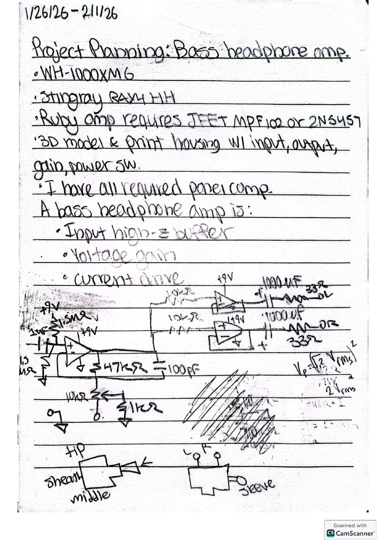
At home I drew up this simple circuit diagram to represent the amplifier and used the LMC66AIN op amp for the initial buffer, and the L272 power op amp for the power output (since each channel can output up to 1A). I first thought of the Ruby headphone amplifier, but wanting to build a custom one, I instead built my own, thinking through a few iterations from online sources such as those implementing a dual-supply through capacitor-buffered voltage divider, but settling on the one shown below:
When connecting everything together on my breadboard and checking with my oscilloscope, everything worked correctly, but when porting everything over to a perfboard to make it permanent, it looked like the output of the LMC662AIN was clipping. I ran out of time in the day, so I finished and vowed to diagnose the problem another day.
I also procrastinated the 3D modeling of the case for this device to later, just in case the newer implementation of the device had dimensions incompatible with a case I designed at that moment. I think best practice is to 3D model the case only once the dimensions of the final electrical components, PCB, perfboard, etc. are finalized.
1/29/26
The following day, I began by probing every node that made sense to probe and used my variable voltage supply instead of the 9V battery just to eliminate another source of uncertainty. I somehow mistook one row for the next one on my solder-able breadboard by the LMC662AIN and the zener diodes I was using to quell high voltage ringing into the headphones were on the wrong side of the capacitors and were experiencing 4.5V bias which meant much more current backwards through them then I expected, and thus I just removed them entirely. When testing, this fixed the issue entirely, but now there was a popping sound on my headphones and some distortion at high volume. I played with the knobs (since I purposely increased the gain on the non-inverting amp in the solder-able iteration) and managed to get a pretty clean output on my headphones with some fiddling around. I ended up using the minimum gain on the potentiometer, so I think I'll swap out my feedback resistor (which is 6.8kohm right now) with a 2.7kohm one.
For the time being though, I'll begin to 3D model the case and the panel that will allow for swapping of the 9V battery, plugging in and out of the headphones and bass, and adjustment of the volume through the potentiometer. In future iterations I might add EQ filters.
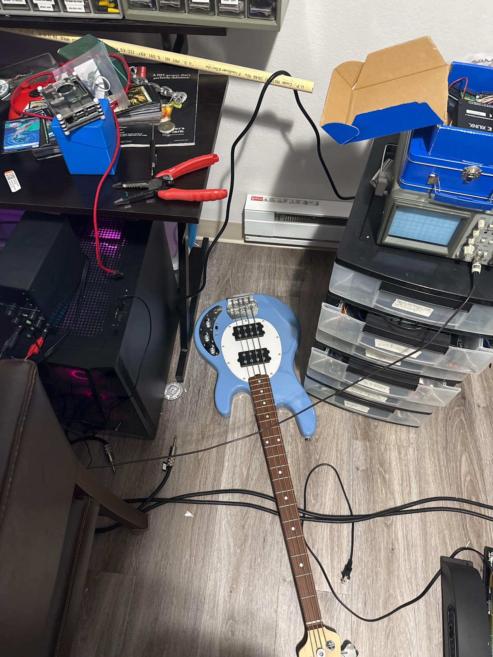
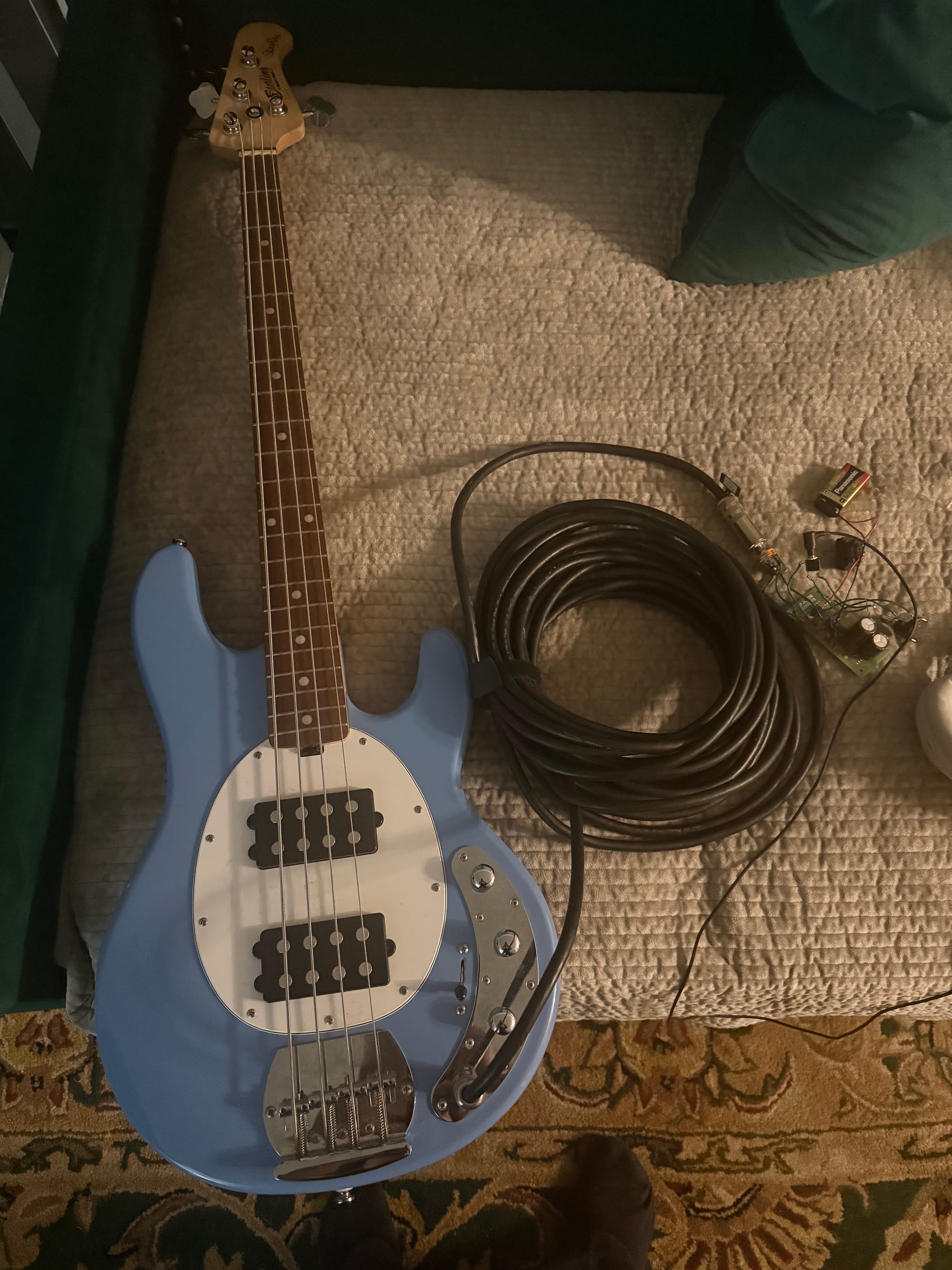
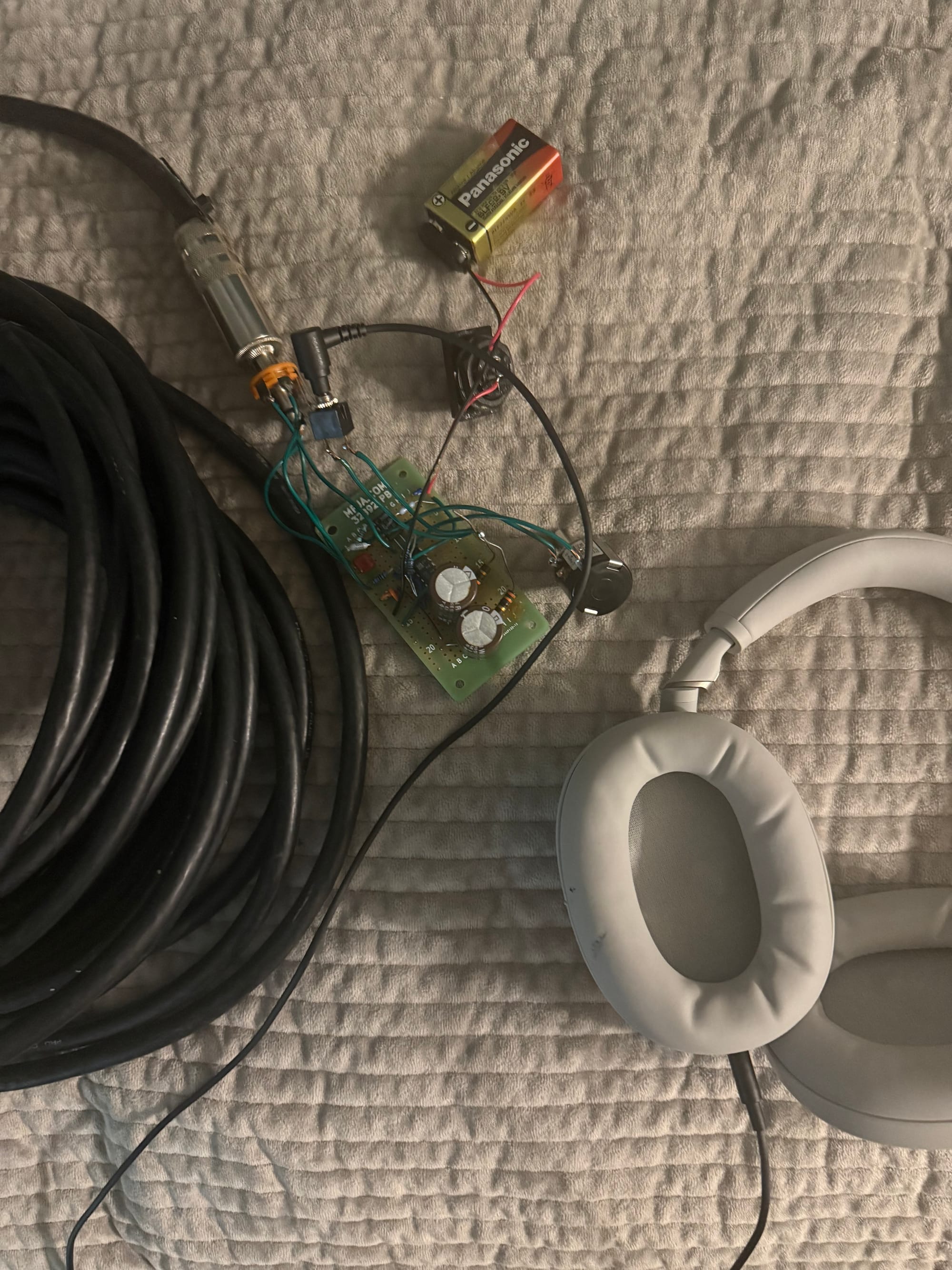
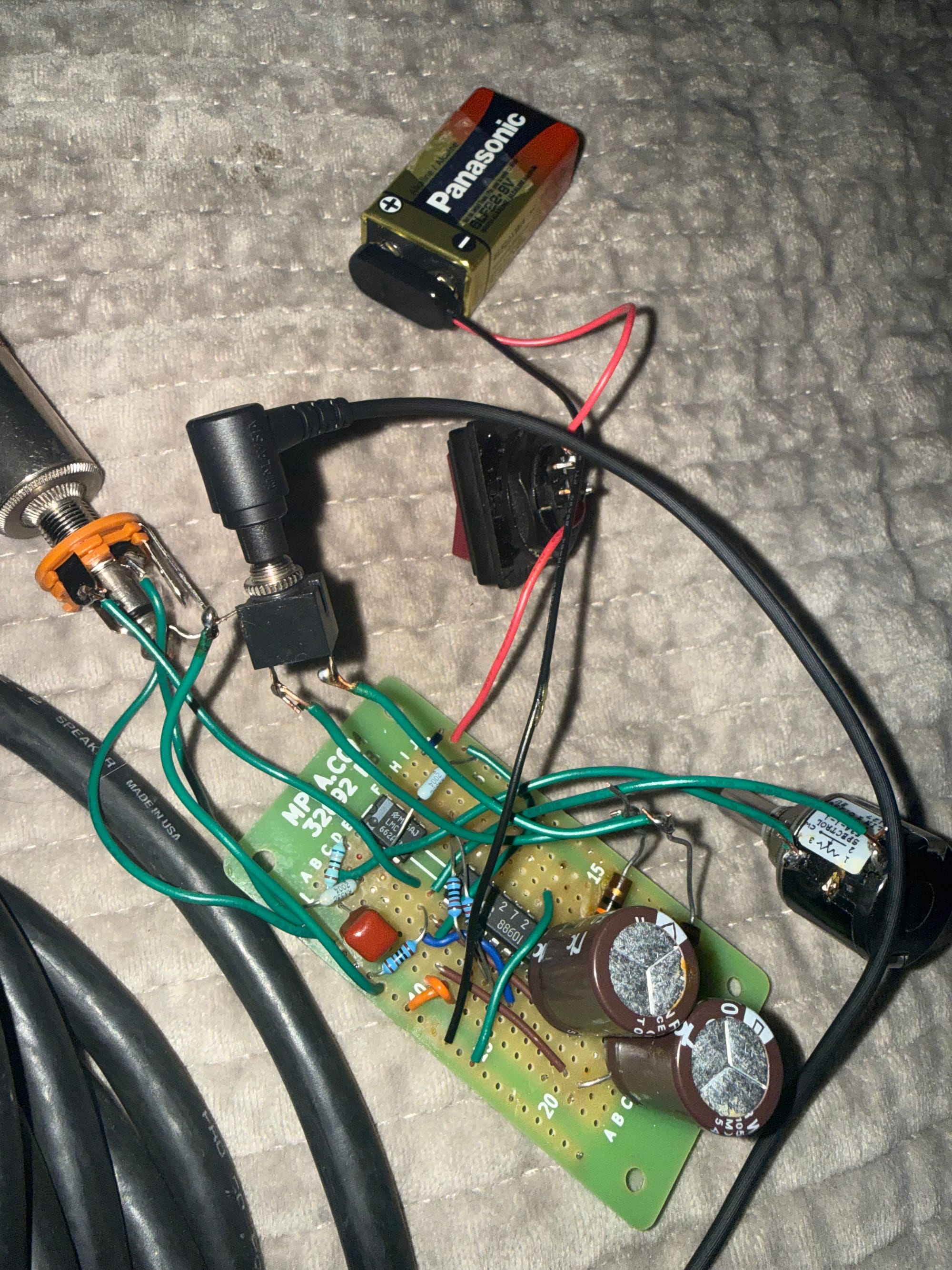
Photos of Setup:
1/30/26
Today I 3D modeled and printed the panel and box for my headphone amp. Since I forgot that the rounded corners were different radii for the panel and box in SolidWorks, I couldn't put a small screw through each corner like I intended, so I just used electrical tape to close the box. In SolidWorks as opposed to Fusion360, I have always been confused by how you couldn't extrude a single sketch twice to create different features, and it has always been frustrating for me. I played around with the Sketch tab, and I figured out I could do the following to get multiple extrudes from one sketch:
- I can create 2 separate extrusions from 1 sketch (or simply reference an existing extrusion face) by drawing a sketch, extruding/revolving once as intended, then creating another sketch, using "convert entities" to convert the desired face into an interactable sketch entity, and then sketching additionally as needed to extrude/revolve again.
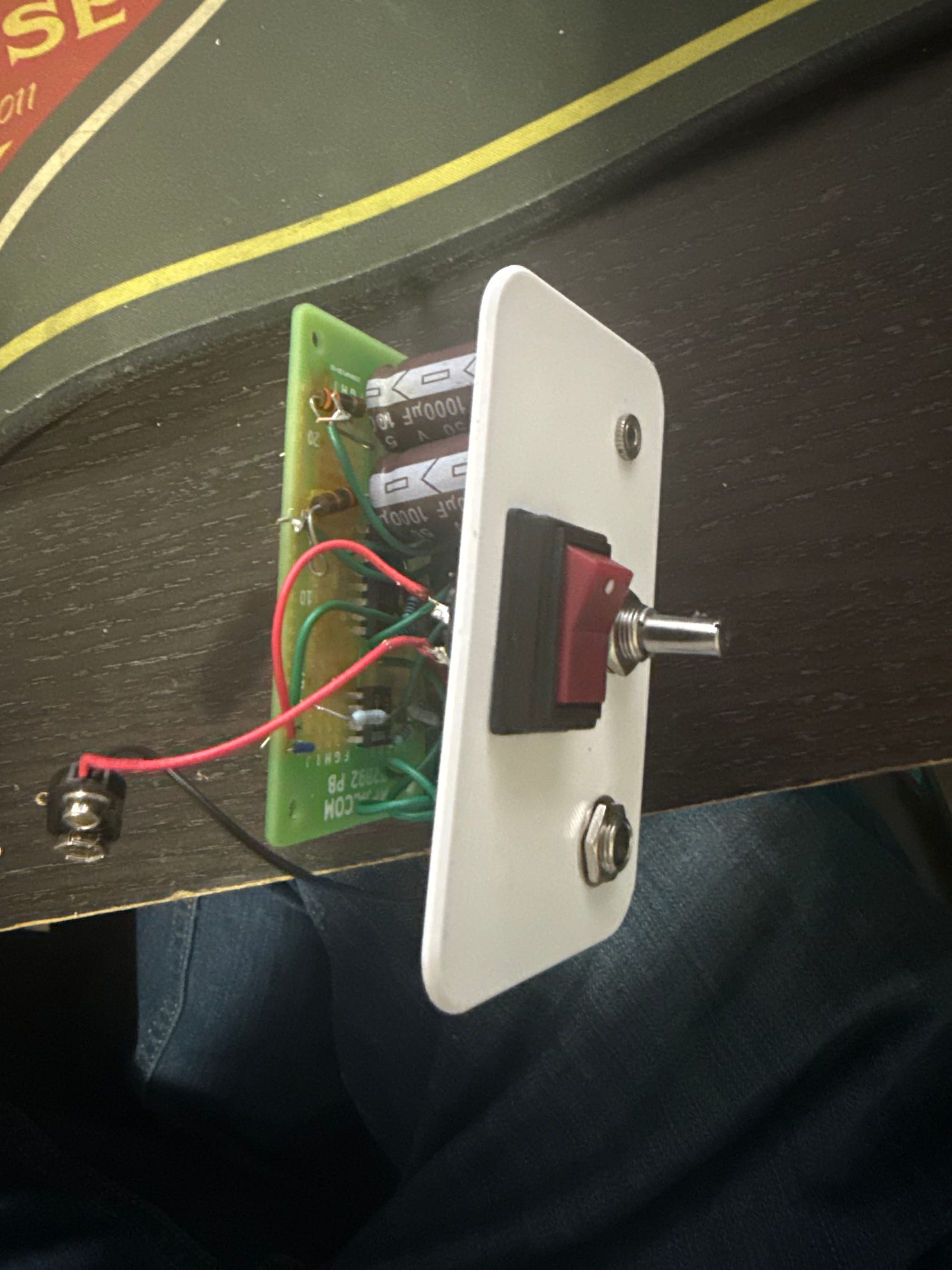
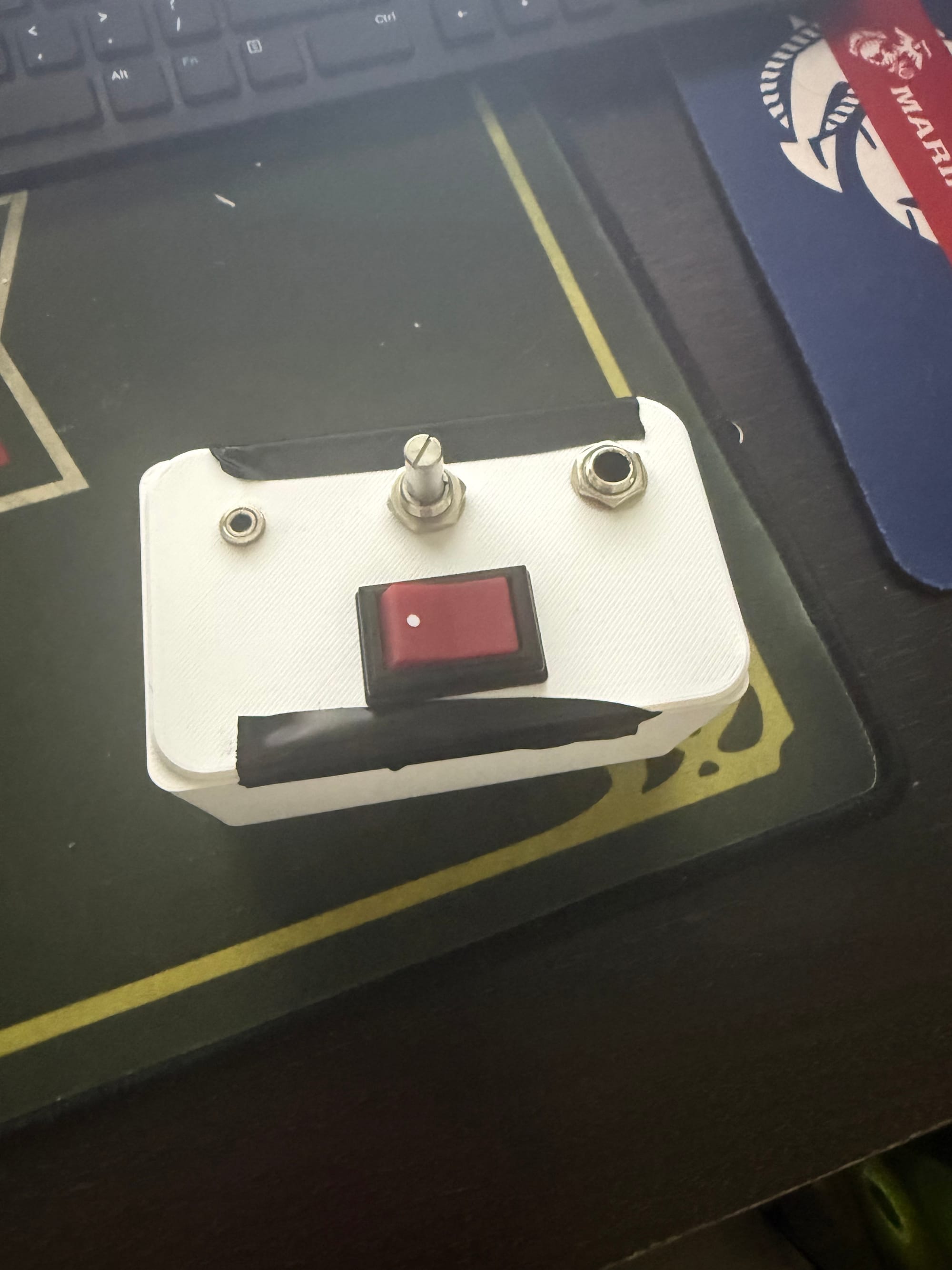
The intermediate step and finished product are below:
Unfortunately, the final headphone amp was difficult to tune, as I had to turn all the knobs on the bass to a specific value AND the potentiometer in order to get it to sound right without popping noises. What's difficult for me to understand now is how the adjustments of the linear pot on the headphone amp are affecting the signal, since it doesn't seem like a flat volume increase like I thought. I think at some point, the whole signal clips out after raising the "volume" enough, with only a small range where an increase on the knob roughly maps to an increase in volume, but not by much. The maximum volume I could reach is not very much, so I'm thinking of looking at the circuit another time to see what could be going on, and perhaps probing the output signal as I sweep the volume knob.
Improvements:
In my next iteration, I plan to:
- Make the enclosure better, with the perfboard actually mounted to the box, and the lid actually mounted to the box
- Implement the Ruby bass headphone amp design
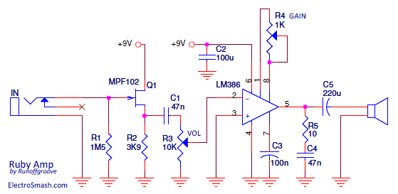
5/15/26
Today and yesterday I completed the above two steps by buying the MPF102 and LM386 required for the project from Vetco, as well as a 10k log potentiometer. I replaced the 1k gain pot with a 10k linear 20 turn pot, but it'll just provide a lower minimum volume with the higher series resistance. This is the exact version I copied:
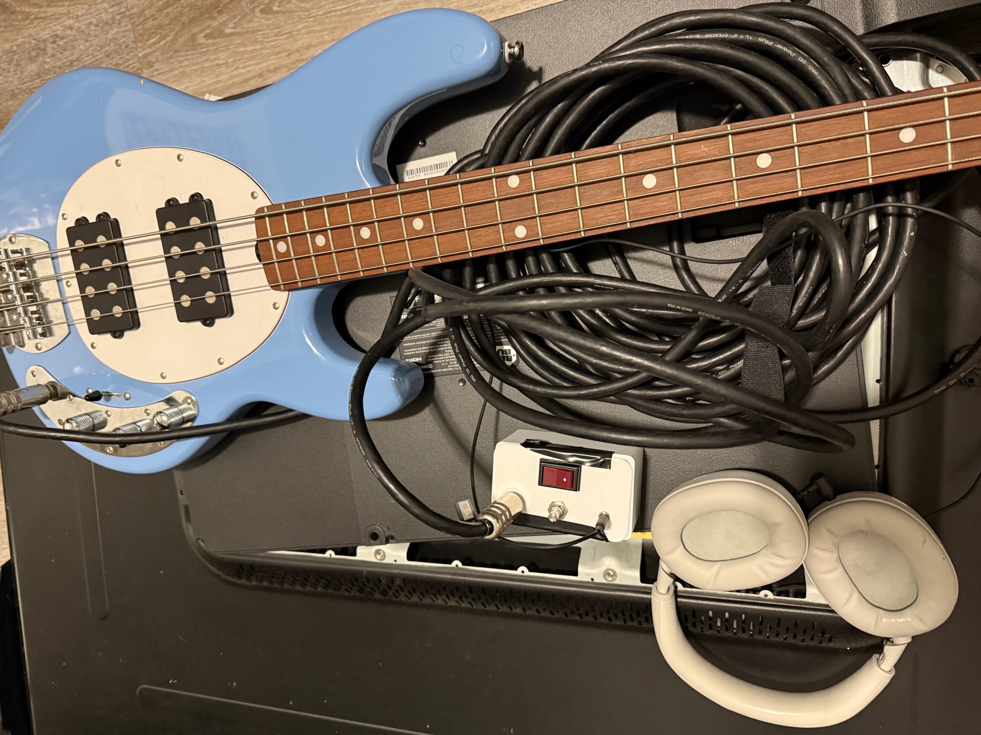
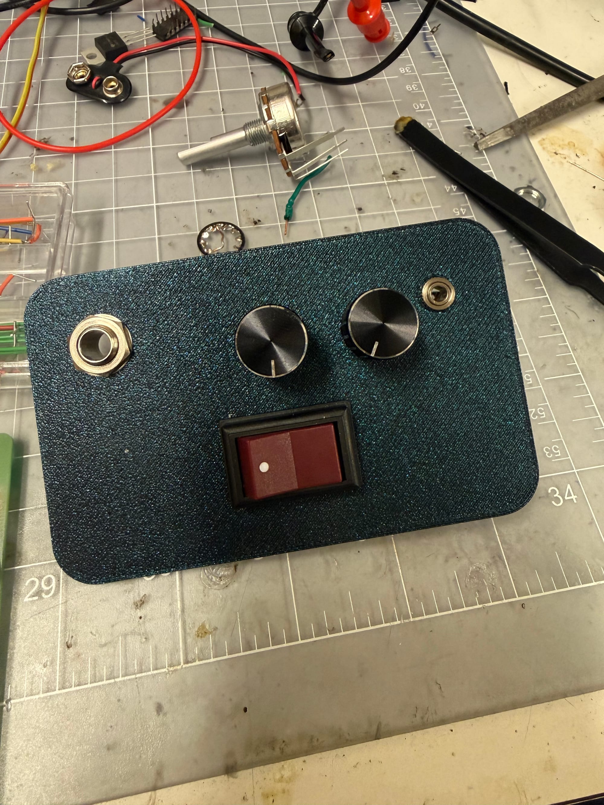
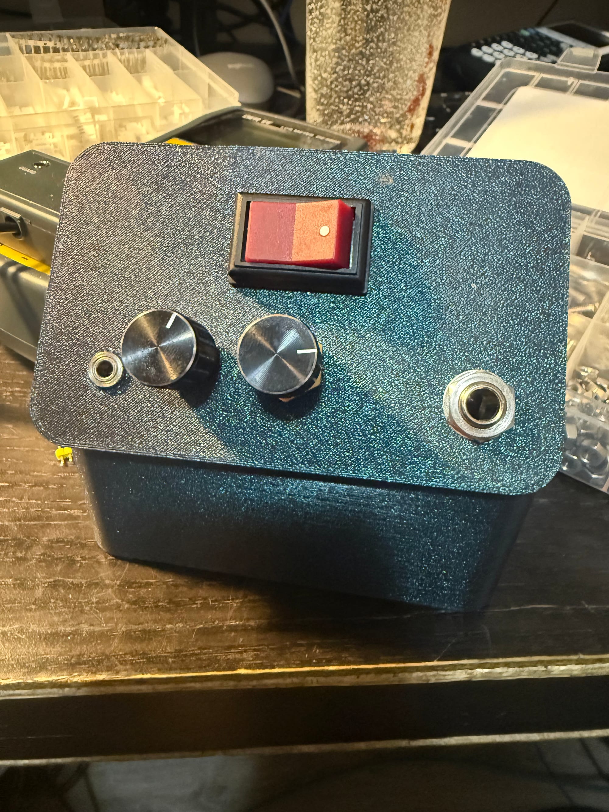
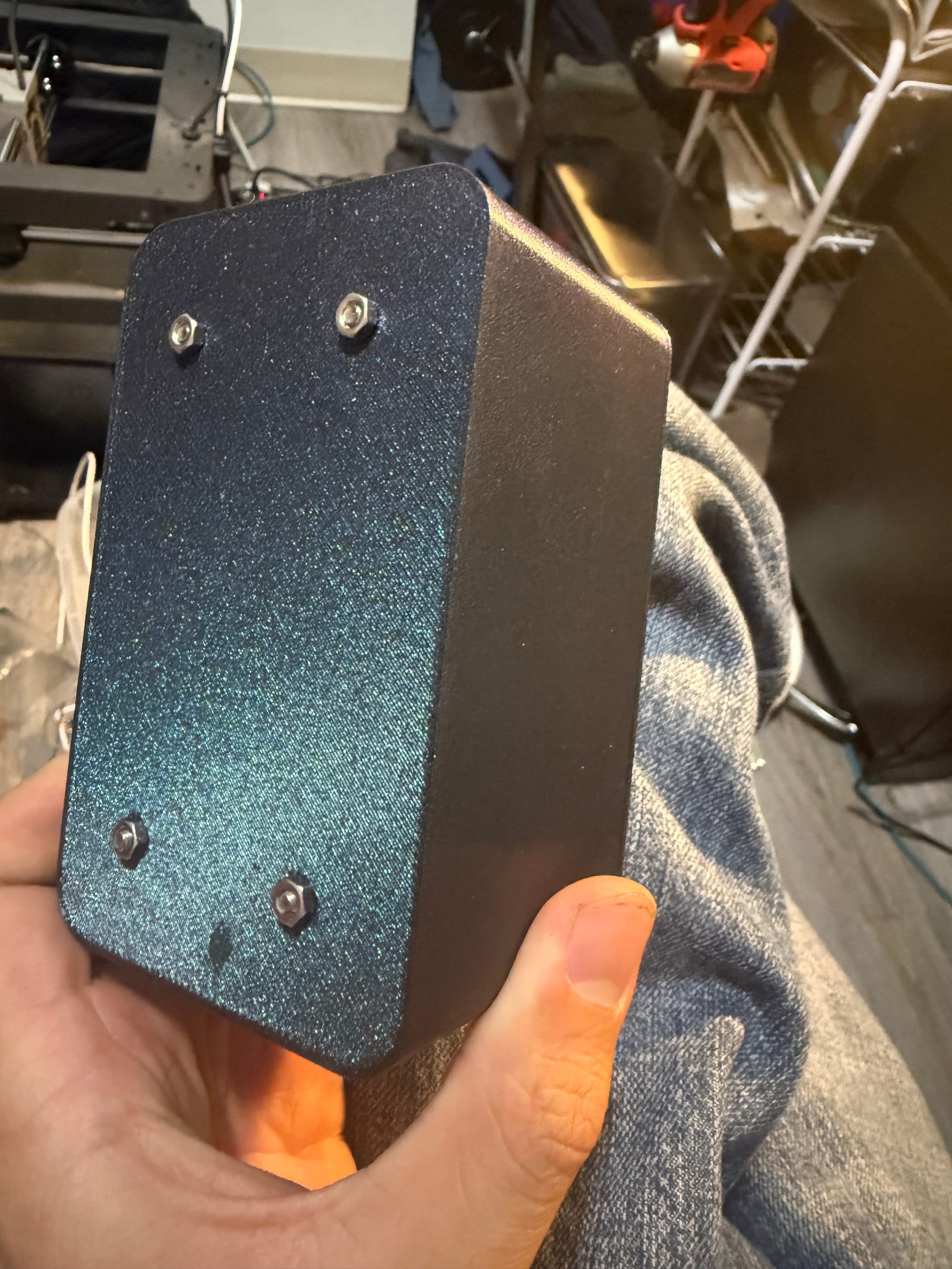
I 3D printed an enclosure with the right holes in the lid and body now to allow mounting of the perfboard onto the enclosure and of the lid onto the enclosure. After mounting all the panel-mount components and soldering everything together, here's how it looks!
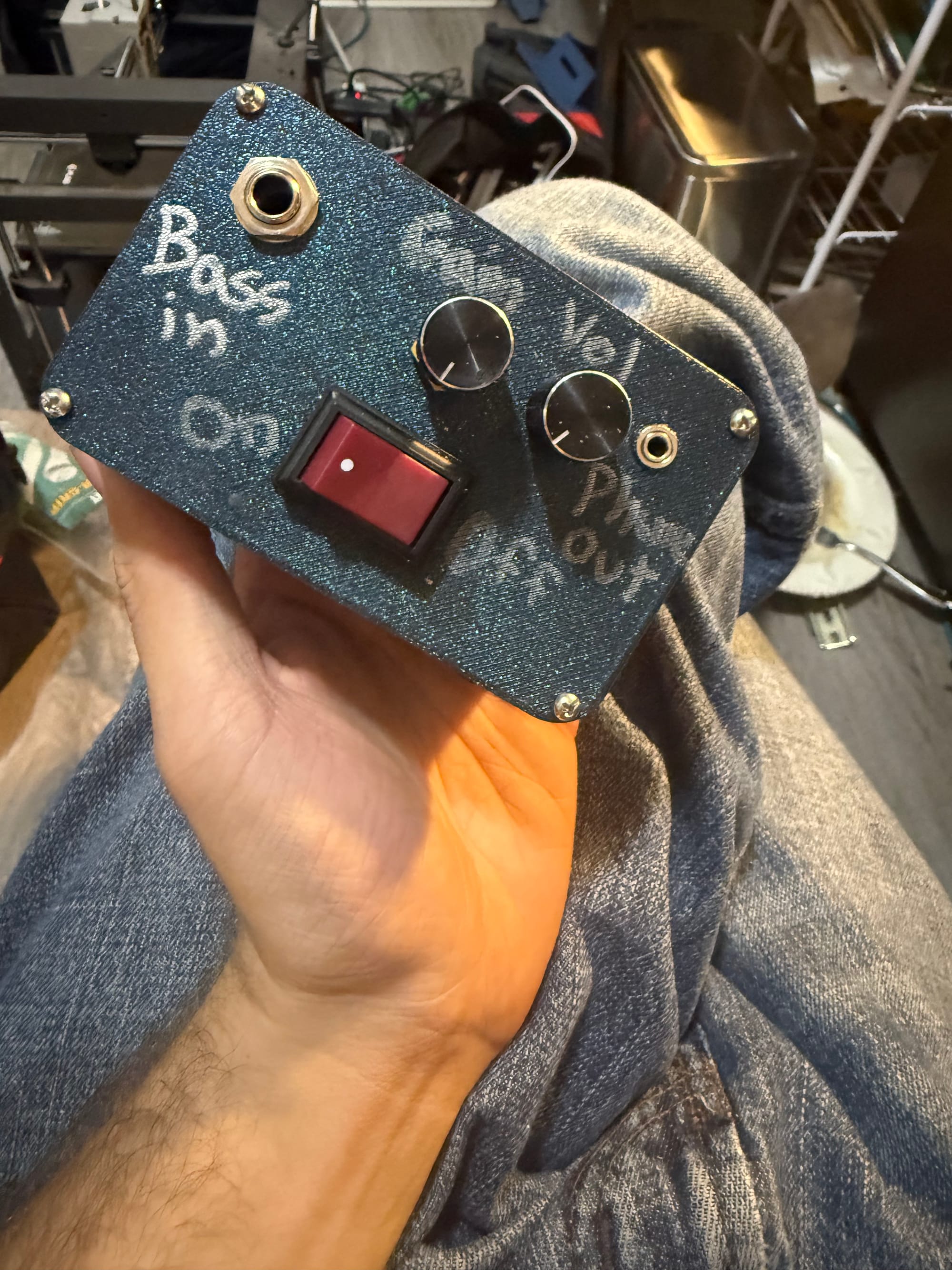
Now just on to testing, which I'll do later on when I have the mono jack back, since I gave it and my bass away.